
Decoding the Wiring Diagram for Start and Run Capacitors
When an air conditioning compressor hums but fails to start, or a condenser fan motor overheats and trips its internal thermal overload, the root cause frequently traces back to the capacitor bank. For HVAC technicians and advanced DIYers, mastering the wiring diagram for start and run capacitors is not just about matching wire colors; it is about understanding the phase-shifting physics that create the rotating magnetic field in single-phase Permanent Split Capacitor (PSC) and Capacitor-Start/Capacitor-Run (CSCR) motors.
As of 2026, while variable-speed ECM motors dominate high-efficiency systems, millions of PSC and CSCR units remain in active service. Troubleshooting these systems requires a methodical approach to the schematic, a solid grasp of microfarad (µF) tolerances, and strict adherence to electrical safety protocols outlined by OSHA's electrical safety standards.
Anatomy of the Dual Run Capacitor Schematic
The most common component in residential and light commercial HVAC systems is the dual run capacitor. Physically, it is a single cylindrical can containing two separate capacitor circuits sharing a common terminal. When reading the wiring diagram, you will encounter three primary terminals on the top plate:
- C (Common): The shared connection point for both the compressor and fan motor run windings. This is typically fed by the 240V line directly from the contactor.
- HERM (Hermetic): Connects exclusively to the start winding of the hermetic compressor.
- FAN: Connects exclusively to the start winding of the condenser fan motor.
Expert Insight: Never assume terminal placement based on physical proximity. While many OEM capacitors (like the widely used Genteq 97F9839) group HERM and FAN on opposite sides of the C terminal, aftermarket replacements vary. Always verify the stamped schematic on the capacitor casing before terminating wires.
Tracing the Circuit: Compressor and Fan
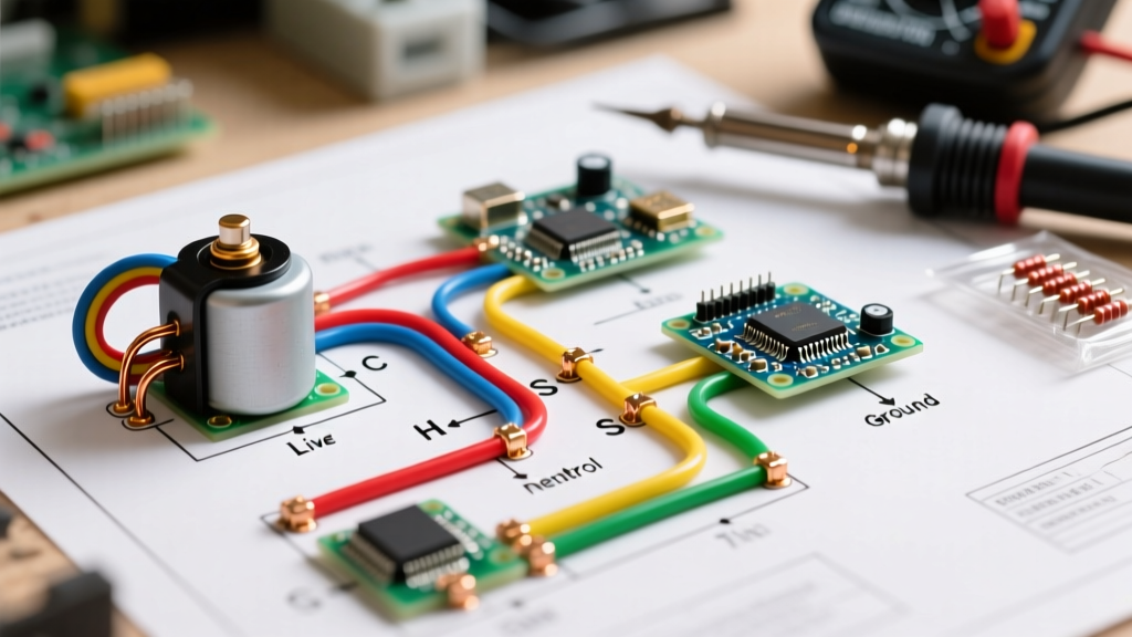
In a standard PSC wiring diagram, Line 1 (L1) from the contactor feeds the run winding of both the compressor and the fan motor. Line 2 (L2) feeds the 'C' terminal on the dual capacitor. The 'HERM' terminal routes back to the compressor's start winding (S), and the 'FAN' terminal routes to the fan motor's start winding. The capacitor shifts the current phase in the start windings by approximately 90 degrees, generating the necessary starting torque and maintaining continuous efficiency.
Troubleshooting Matrix: Symptoms vs. Diagram Faults
Visual inspection and schematic tracing are your first lines of defense. Use the following diagnostic matrix to correlate physical symptoms with specific wiring or component failures.
| Symptom | Diagram Trace Point | Expected Multimeter Reading | Probable Fault & Action |
|---|---|---|---|
| Compressor hums, trips breaker | Contactor L2 to HERM terminal | ~45 µF (±6%) | Open HERM circuit or weak compressor run cap. Test capacitance. |
| Fan runs, compressor does not | Compressor 'S' terminal to HERM | Continuity (<5 Ohms) | Internal compressor start winding open. Capacitor is likely fine. |
| Fan motor overheats/shuts off | FAN terminal to Fan 'S' wire | ~5 µF (±6%) | FAN cap section degraded. Check for bulging top or oil leak. |
| System runs, but amps are 20% high | L1/L2 across contactor | 240V AC ±10% | Low voltage or high ESR in capacitor causing poor phase shift. |
Step-by-Step Capacitor Diagnostics
To accurately troubleshoot using the wiring diagram, you must isolate the component from the circuit. Testing a capacitor in-circuit will yield false readings due to parallel paths through the motor windings.
1. Lockout/Tagout and Discharge
Disconnect all power at the service panel and verify zero energy at the contactor using a CAT III or CAT IV rated multimeter (e.g., Fluke 116 or Fieldpiece SC440). Never short a capacitor with a screwdriver. This violent discharge damages the internal metallized polypropylene film dielectric. Instead, use a 20,000-ohm, 5-watt wirewound resistor across the C-HERM and C-FAN terminals for 5 seconds to safely bleed the stored voltage.
2. Microfarad Testing and the EIA-456-A Standard
Remove the spade connectors from the capacitor. Set your meter to the capacitance (µF) setting. According to the EIA-456-A standard, a standard HVAC run capacitor has a tolerance of ±6%. If you are testing a 45+5 µF capacitor:
- The HERM side must read between 42.3 µF and 47.7 µF.
- The FAN side must read between 4.7 µF and 5.3 µF.
If the reading drops below 42.3 µF, the dielectric has degraded. In 2026, premium replacements like the AmRad TUFF (Turbo 200x) series cost between $25 and $40, offering vastly superior heat dissipation compared to standard $12 OEM equivalents.
Integrating Start Capacitors and Potential Relays
While run capacitors stay in the circuit continuously, start capacitors are designed for high-torque, short-duration bursts (typically under 3 seconds). They use an electrolytic dielectric, allowing for massive capacitance values (e.g., 200-300 µF) in a small package, but they will literally explode if left in the circuit continuously.
The Hard Start Kit Wiring Diagram
When a compressor suffers from 'hard starting' due to wear, liquid slugging, or low ambient head pressure, technicians install a hard start kit (such as the SUPCO SPP6E). The wiring diagram for a start capacitor and potential relay involves the following connections:
- Relay Coil: Wired in parallel across the compressor's Start (S) and Run (R) windings. It monitors the back-EMF (electromotive force) generated by the spinning rotor.
- Relay Contacts (Normally Closed): Wired in series with the start capacitor.
- Start Capacitor: Wired in series with the relay contacts and the compressor's Start (S) terminal.
How it works: Upon startup, the closed relay contacts route maximum current through the start capacitor, providing a massive phase shift and torque boost. As the compressor reaches roughly 75% of its rated RPM, the back-EMF across the start winding spikes. This voltage energizes the relay coil, snapping the contacts open and instantly dropping the start capacitor out of the circuit. A failure in the potential relay will leave the start capacitor engaged, resulting in catastrophic venting of the capacitor's electrolyte within seconds.
Common Wiring Edge Cases and 'Gotchas'
Even seasoned technicians fall victim to subtle wiring errors when interpreting complex schematics. Watch out for these specific edge cases:
- The Bleed Resistor Omission: Unlike run capacitors, start capacitors require a 15,000 to 20,000-ohm bleed resistor wired in parallel across their terminals. This dissipates the residual voltage between start cycles. If your wiring diagram shows a bleed resistor and it is missing or burnt open, the start capacitor can retain a lethal charge or fail to reset properly for the next short-cycle start.
- Swapping HERM and FAN: Wiring the 5 µF fan circuit to the compressor and the 45 µF compressor circuit to the fan will cause the fan motor to run at dangerous speeds (risking blade detachment) while the compressor starves for starting torque, tripping the breaker instantly.
- Daisy-Chaining Grounds: The capacitor casing is not a grounding point. Ensure all motor ground wires are routed back to the main equipment ground lug per NFPA 70 (NEC) Article 250.
Safety, Efficiency, and Code Compliance
Troubleshooting electrical components requires strict adherence to safety standards. The U.S. Department of Energy emphasizes that poorly maintained electrical connections and failing capacitors not only cause system breakdowns but drastically reduce SEER2 efficiency ratings, leading to severe energy waste.
Always verify that your replacement capacitor matches the original equipment's voltage rating (e.g., 440V AC) and microfarad rating exactly. Upgrading from a 370V to a 440V capacitor is acceptable and often recommended for longevity in high-heat environments, but altering the microfarad rating will alter the motor's magnetic field geometry, causing excessive amperage draw and premature winding failure. By combining a rigorous reading of the wiring diagram with precise multimeter diagnostics, you ensure reliable, code-compliant operation for the lifespan of the HVAC system.