
The Inductive Challenge: Why Motor Panels Are Different
Designing an electrical panel for lighting or receptacles is a straightforward exercise in ohms law and continuous load calculations. However, when you begin interpreting wiring diagrams for electric motors, you are dealing with highly inductive loads characterized by massive inrush currents. A standard 10-horsepower (HP) 3-phase motor can draw up to 600% of its Full Load Amps (FLA) during startup. If you size your panel breaker using standard Article 210 rules, the breaker will trip instantly upon motor startup.
To properly wire and protect motor circuits, electrical professionals must rely on National Electrical Code (NEC) Article 430. This guide breaks down how to read motor control schematics, size panel breakers, and integrate modern Variable Frequency Drives (VFDs) into your distribution panels in 2026.
Decoding Wiring Diagrams for Electric Motors: NEMA vs. IEC
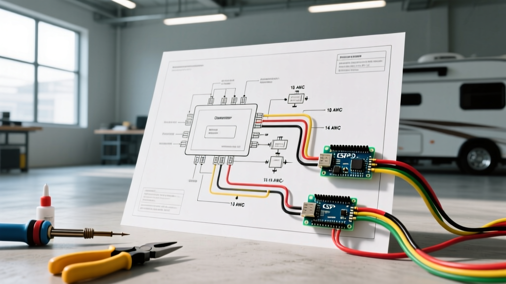
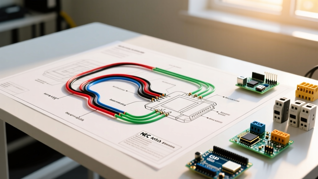
Before pulling wire, you must understand the schematic language. In North America, industrial panels predominantly use NEMA (National Electrical Manufacturers Association) ladder-style diagrams. European and modern OEM equipment often uses IEC block diagrams.
- NEMA Ladder Logic: Power circuits (L1, L2, L3) run vertically on the left. Control circuits (typically 120VAC or 24VDC) run horizontally as 'rungs'. You will see symbols for contactors (M), overload relays (OL), and timing relays (TR). NEMA components, like the Eaton Freedom Series C25 contactors, are physically larger and built for rugged, high-fault environments.
- IEC Block Diagrams: Components are drawn in functional blocks. A contactor coil (A1, A2) and its associated auxiliary contacts (13, 14 for NO; 21, 22 for NC) are drawn where they logically fit in the circuit, not necessarily near the physical coil. IEC components, such as the Siemens Sirius 3RT2 series, are compact and modular.
Expert Tip: When tracing a NEMA wiring diagram for an electric motor, always start at the control circuit transformer secondary (X1 and X2). Verify the control voltage before applying 480V to the main power lugs. Applying 480V to a 120V control coil will result in an immediate, catastrophic failure.
Panel Breaker Sizing: The NEC Article 430 Framework
The most common mistake junior electricians make is sizing the panel breaker to the wire ampacity. For motor circuits, the breaker's primary job is short-circuit and ground-fault protection, not overload protection. The overload protection is handled by the thermal or magnetic overload relay located inside the motor starter enclosure.
According to NEC Table 430.52, the maximum rating for an inverse-time circuit breaker protecting a standard AC motor is 250% of the motor's FLA.
Motor Branch Circuit Sizing Matrix (460V, 3-Phase)
| Motor HP | FLA (NEC Table 430.250) | Min Wire Ampacity (125% FLA) | Recommended THHN Wire | Max Inverse Time Breaker (250%) | Overload Relay Setting (115% FLA) |
|---|---|---|---|---|---|
| 3 HP | 4.8A | 6.0A | 14 AWG | 15A | 5.5A |
| 7.5 HP | 11.0A | 13.75A | 12 AWG | 25A | 12.6A |
| 10 HP | 14.0A | 17.5A | 12 AWG | 35A (Next size up: 40A) | 16.1A |
| 25 HP | 34.0A | 42.5A | 8 AWG | 85A (Next size up: 90A) | 39.1A |
| 50 HP | 65.0A | 81.25A | 3 AWG | 162A (Next size up: 175A) | 74.7A |
Note: If the calculated breaker size does not correspond to a standard breaker size listed in NEC 240.6, you are permitted to round up to the next standard size (e.g., 85A calculation allows a 90A breaker).
VFD Panel Integration vs. Direct-On-Line (DOL) Starters
In 2026, the shift toward energy efficiency means Variable Frequency Drives (VFDs) like the Yaskawa GA800 or Allen-Bradley PowerFlex 527 are replacing traditional DOL starters. The wiring diagrams for electric motors controlled by VFDs require a fundamentally different panel approach.
Key VFD Panel Wiring Rules:
- Input Fusing vs. Breakers: VFD manufacturers strongly recommend using fast-acting semiconductor fuses (like Bussmann FWH series) on the input side rather than standard thermal-magnetic breakers. VFDs draw non-linear current with high harmonic distortion, which can cause nuisance trips on standard panel breakers.
- Output Cable Selection: Standard THHN wire is insufficient for VFD-to-motor runs due to reflected wave phenomena (dv/dt spikes). You must use specialized VFD cable (e.g., Southwire VFD-TRAY) with an oversized ground and continuous corrugated aluminum armor to shield control signals from electromagnetic interference (EMI).
- Bypass Contactors: Critical infrastructure panels often include a 3-contactor bypass diagram. If the VFD fails, the control logic drops out the VFD isolation contactors and engages a DOL contactor to keep the motor running directly across the line.
9-Lead Dual Voltage Motor Wiring: Wye vs. Delta
Many industrial 3-phase motors feature 9 external leads (T1 through T9), allowing them to be wired for high voltage (460V) or low voltage (230V). Understanding the wiring diagrams for these electric motors is critical, as miswiring will result in severe damage.
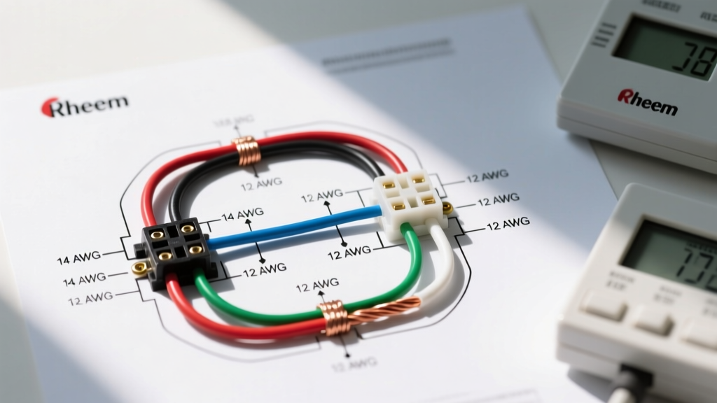
- Low Voltage (230V) - Parallel Wye: The internal coils are wired in parallel. You will group leads (T1, T7, T6 to L1), (T2, T8, T4 to L2), and (T3, T9, T5 to L3).
- High Voltage (460V) - Series Wye: The internal coils are wired in series. You will connect L1 to T1, L2 to T2, L3 to T3. Then, you must join and insulate T4-T7, T5-T8, and T6-T9 using high-temperature silicone wire nuts or heat shrink.
Failure Mode Alert: If you wire a motor in the Wye configuration but the nameplate specifies a Delta configuration for that voltage, the motor will run, but it will draw excessive current, overheat, and trip the overload relay within minutes under load. Always cross-reference the physical nameplate diagram, not just the generic manual.
Panel Terminations & Torque Verification
A perfectly calculated wiring diagram is useless if the physical panel connections are flawed. Under NEC 110.14(D), terminals rated 100A or less must be tightened to the manufacturer's specified torque using a calibrated torque tool.
For example, when landing 8 AWG stranded wire on a 40A Eaton Type HACR breaker, the required torque is typically 45 in-lbs. Stranded wire entering motor starter lugs should be terminated with crimped pin ferrules to prevent wire splaying, which reduces the contact surface area and creates localized resistance heating. According to Fluke's motor troubleshooting guidelines, loose panel connections account for over 30% of premature motor starter failures, easily identifiable via thermal imaging showing a 15°C+ delta above ambient phase temperatures.
Expert Troubleshooting FAQ
Can I use a standard lighting breaker for a motor circuit?
No. You must use an HACR (Heating, Air Conditioning, and Refrigeration) rated breaker or a breaker explicitly listed for motor starting currents. Standard breakers may interpret the 6-to-8-cycle magnetic inrush of a motor as a dead short and trip instantaneously on the magnetic trip curve.
Why does my panel breaker trip, but the motor overload does not?
This indicates a short circuit or ground fault, not an overload. The overload relay is designed to trip slowly on thermal buildup (e.g., a jammed conveyor belt causing 130% FLA draw). The panel breaker trips instantly on massive current spikes (e.g., a dead phase-to-ground short caused by degraded motor winding insulation). Use a megohmmeter (Megger) to test winding insulation resistance to ground; it should read >100 Megohms for a healthy 460V motor.
How do I integrate a PLC into a NEMA motor starter diagram?
Modern panels use a PLC output card (sourcing 24VDC) to trigger an interposing relay (like an IDEC RU4S). The dry contacts of the interposing relay then switch the 120VAC control voltage to the NEMA contactor coil (A1/A2). This isolates the sensitive PLC logic from the inductive kickback generated when the motor contactor drops out.
For deeper insights into industrial motor standards and physical enclosure sizing, refer to the NEMA Motors and Generators (MG 1) standard documentation. Properly executing wiring diagrams for electric motors ensures panel longevity, personnel safety, and uninterrupted industrial operations.