
The 'Odd Number' Dilemma in Vehicle Audio
Designing a high-output car audio system typically involves pairs of subwoofers. Two or four subs make impedance matching a straightforward exercise in basic series and parallel wiring. However, installing exactly three subwoofers—often dictated by custom down-firing crew cab enclosures, asymmetrical trunk layouts, or specific SPL (Sound Pressure Level) competition rules—introduces a mathematical headache. When you search for a wiring diagram for 3 subwoofers, you quickly realize that standard wiring topologies result in awkward, unstable, or inefficient impedance loads.
In 2026, with car audio amplifiers pushing higher efficiency and tighter thermal tolerances, feeding an amplifier an unstable load like 1.33 ohms or 0.67 ohms will instantly trigger protection circuits or cause catastrophic MOSFET failure. This vehicle-specific guide breaks down the exact impedance math, amplifier matching strategies, and electrical upgrades required to safely wire three subwoofers in your car, truck, or SUV.
Understanding Voice Coil Configurations
Before drawing any wiring diagrams, you must identify the voice coil topology of your subwoofers. The industry standard revolves around two types:
- Single Voice Coil (SVC): Each subwoofer has one set of positive and negative terminals. A 4-ohm SVC sub presents exactly 4 ohms.
- Dual Voice Coil (DVC): Each subwoofer has two independent voice coils, offering four terminals per sub. This provides exponentially more wiring flexibility, which is absolutely mandatory when wiring an odd number like three.
Expert Rule of Thumb: Never attempt to wire three SVC subwoofers together on a single amplifier channel unless you are using a specialized multi-channel amplifier with independent impedance monitoring on each channel. For a monoblock (Class D) amplifier, DVC subwoofers are a strict requirement.
Impedance Matrix: Wiring 3 Subwoofers
The following matrix illustrates the final impedance load presented to the amplifier based on the subwoofer type and wiring topology. This data is critical for matching your enclosure to your amplifier's minimum stable ohm rating.
| Subwoofer Type | Wiring Topology | Final Impedance Load | Amplifier Stability Requirement |
|---|---|---|---|
| 3x SVC 4-Ohm | All Parallel | 1.33 Ohms | 1-Ohm Stable (High Risk) |
| 3x SVC 4-Ohm | All Series | 12.0 Ohms | 4-Ohm Stable (Severe Power Loss) |
| 3x DVC 2-Ohm | All Coils Parallel | 0.33 Ohms | Unsupported (Amp Destruction) |
| 3x DVC 2-Ohm | Series-Parallel (Optimal) | 3.0 Ohms | 2-Ohm Stable (Highly Recommended) |
| 3x DVC 4-Ohm | Coils Series / Subs Parallel | 2.67 Ohms | 2-Ohm Stable (Safe) |
| 3x DVC 4-Ohm | All Coils Parallel | 0.67 Ohms | Unsupported (Amp Destruction) |
Scenario A: Three DVC 2-Ohm Subwoofers (The Sweet Spot)
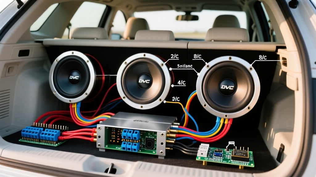
This is the most common and efficient configuration for a 3-sub setup (e.g., three Skar Audio EVL-15 D2 or Sundown Audio SAZ-15 D2 subwoofers). You have a total of six 2-ohm coils.
- Step 1: Wire the two coils on Subwoofer 1 in series (2 + 2 = 4 ohms). Repeat for Subwoofer 2 and Subwoofer 3.
- Step 2: You now have three 4-ohm loads. Wire all three subwoofers in parallel.
- Step 3: The math: 4 ohms divided by 3 subs = 1.33 ohms.
Alternative (Safer) Topology: Wire three coils in series (6 ohms). Wire the remaining three coils in series (6 ohms). Parallel the two 6-ohm strings together. Result: 3.0 ohms. This allows a standard 2-ohm stable amplifier to run slightly above its minimum threshold, generating significantly less heat and extending the lifespan of the amp.
Scenario B: Three DVC 4-Ohm Subwoofers
If you are using DVC 4-ohm subs (e.g., JL Audio 12W7AE-3 D4 equivalents), wire each sub's coils in series to create an 8-ohm load per sub. Wire the three subs in parallel. The final load is 8 / 3 = 2.67 ohms. This is a phenomenal load for almost any high-quality Class D monoblock amplifier, keeping the power supply efficient and the output transistors cool.
Amplifier Matching for 3-Sub Setups
When wiring three subwoofers, you must calculate the total RMS power required and match it to an amplifier that can handle the resulting odd impedance. As of 2026, here are the top-tier amplifier recommendations for 3-sub configurations:
- Taramps MD 3000.1 (Approx. $599): A Brazilian-engineered powerhouse that is genuinely 1-ohm stable. If your wiring math results in a 1.33-ohm load (three DVC 2-ohm subs wired in standard series/parallel), this amp will push roughly 2,200 watts RMS at 1.33 ohms without triggering thermal protection, provided you have adequate cooling.
- Skar Audio RP-3500.1D (Approx. $449): Rated for 3,500 watts at 1 ohm. It handles 1.33-ohm loads comfortably. Its strapping capability makes it ideal if you decide to add a fourth subwoofer later.
- Sundown Audio SFB-3500D (Approx. $1,299): For audiophiles prioritizing low THD (Total Harmonic Distortion) over raw SPL. It is optimized for 2-ohm to 4-ohm loads, making it perfect for the 2.67-ohm or 3.0-ohm wiring topologies mentioned above.
Power Delivery: Wire Gauge and the 'Big 3' Upgrade
Wiring three subwoofers usually implies a system drawing between 2,000 and 4,500 watts. At 14.4 volts, a 3,000-watt system pulls over 208 amps of continuous current. Standard factory vehicle wiring will melt, and the factory alternator will fail to keep up, resulting in headlight dimming and amplifier clipping.
Selecting the Right Wire Gauge
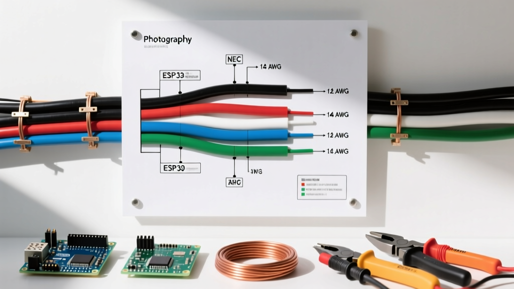
According to American Wire Gauge Standards, current capacity is strictly tied to wire diameter and material. You must use OFC (Oxygen-Free Copper), not CCA (Copper-Clad Aluminum). CCA has 40% higher resistance and is a known fire hazard in high-current car audio applications.
- 0 AWG OFC: Required for the main power run from the battery to the distribution block for systems up to 3,500W.
- 1/0 AWG OFC: Recommended for systems exceeding 3,500W or for runs longer than 16 feet (common in extended cab trucks).
- 4 AWG OFC: Minimum requirement from the distribution block to individual amplifiers.
The 'Big 3' Electrical Upgrade
To sustain the massive current demands of a 3-subwoofer array, you must perform the 'Big 3' upgrade. This involves replacing or supplementing three critical factory ground and power paths with 1/0 AWG OFC wire:
- Alternator Positive to Battery Positive: Eliminates voltage drop between the charging source and the storage battery.
- Battery Negative to Vehicle Chassis: Ensures the main power reservoir has a zero-resistance path to the vehicle's ground plane.
- Engine Block to Vehicle Chassis: Critical because the alternator is grounded to the engine block; this completes the high-current circuit back to the battery.
For a deeper understanding of DC grounding principles and chassis safety, refer to the electrical safety frameworks outlined by the NFPA Electrical Safety Standards, which heavily emphasize minimizing ground loop resistance in high-amperage mobile environments.
Step-by-Step Vehicle Wiring Execution
Follow this exact sequence to wire your 3-subwoofer enclosure safely:
- Disconnect the Battery: Always remove the negative terminal first to prevent short circuits.
- Run Main Power: Route your 0 AWG OFC power wire through the firewall using a rubber grommet. Install an ANL fuse holder within 18 inches of the battery positive terminal. For a 3,000W system, use a 350A ANL fuse.
- Install Distribution Block: Mount a fused distribution block near the amplifier. Run 4 AWG OFC from the block to the amp's positive terminal.
- Wire the Subwoofers (Internal Box): Using 12 AWG or 10 AWG speaker wire, wire the voice coils according to your chosen impedance matrix (e.g., the 3.0-ohm series-parallel topology). Solder all connections and use heat shrink tubing. Terminal cups vibrate loose over time; solder is mandatory for competition-level SPL.
- Connect Speaker Wire to Amp: Run the final parallel leads from the enclosure's terminal cup to the amplifier's speaker outputs. Ensure the impedance matches your multimeter reading.
- Set the Gain: Use a digital multimeter and an oscilloscope (or a true RMS voltmeter) to set the amplifier gain. Do not rely on your ears. For a 3.0-ohm load on a 3,000W amp, calculate the target AC voltage using the formula: V = √(P × R). √(3000 × 3.0) = √9000 = 94.8 Volts AC.
Troubleshooting: Thermal Compression and Edge Cases
Even with a perfect wiring diagram for 3 subwoofers, physical realities inside the vehicle cabin can cause issues.
- Thermal Compression: When voice coils heat up, their resistance increases. A 3.0-ohm load might climb to 4.5 ohms during heavy use, causing the amplifier to output less power. This is normal, but if your output drops by more than 3dB, you need more cooling or a larger amplifier headroom.
- Clipping vs. Impedance Drops: If your amplifier goes into protect mode only on heavy bass transients (like 30Hz sine waves), your impedance is likely dropping below the amplifier's minimum threshold due to the subwoofer's resonant frequency (Fs) characteristics. Voice coil inductance (Le) causes impedance to rise at higher frequencies, but at Fs, impedance drops to the DC resistance (Re). Always measure impedance with a multimeter while the sub is resting, but understand that dynamic impedance fluctuates.
- Phase Cancellation: With three subwoofers, if one is wired out of phase (positive to negative), it will act as an acoustic short circuit, canceling the output of the other two. Always verify phase alignment using a 9V battery test or a dedicated phase tester tool before sealing the enclosure.
Final Thoughts on System Synergy
Wiring three subwoofers in a vehicle requires abandoning standard 'plug-and-play' mentalities. By leveraging DVC configurations to manipulate the final impedance load into a safe 2-ohm to 3-ohm window, upgrading your vehicle's electrical infrastructure with the Big 3, and meticulously setting your amplifier gain via mathematical formulas, you can achieve a reliable, earth-shattering low-frequency response. For further reading on how speaker impedance interacts with amplifier damping factor, consult the Audioholics Speaker Impedance Guide.