
The Fatal Flaw in Residential Blueprints
Many DIY van lifers, Skoolie builders, and Airstream renovators begin their electrical planning by downloading a standard circuit diagram for house wiring. The logic seems sound on the surface: you are essentially building a 'house' on wheels, so residential 120V AC branch circuit rules should apply. However, blindly applying NEC Article 210 (standard residential branch circuits) to a vibrating, dual-voltage steel tube rolling down the highway at 70 mph is a recipe for catastrophic failure, electrical fires, or fried inverters.
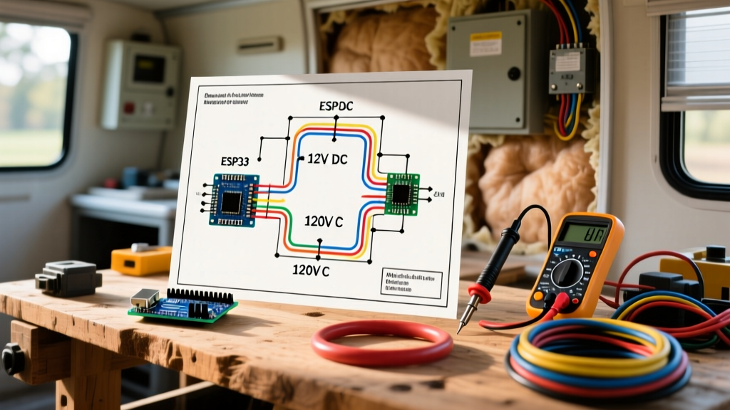
A residential blueprint assumes a static environment, a single voltage phase (120V/240V split-phase AC), and a direct connection to an earth ground rod. An RV or camper van operates in a dynamic, high-vibration environment with a dual-voltage architecture (12V DC and 120V AC) and relies on a floating chassis ground. As of the 2026 manufacturing standards outlined by the Recreational Vehicle Industry Association (RVIA), the integration of high-capacity lithium battery banks and hybrid inverter-chargers requires a fundamental departure from residential wiring logic.
AC vs. DC: The Dual-Voltage Reality
In a standard home, your lighting, outlets, and appliances all run on 120V AC. In a vehicle conversion, you are managing two entirely separate electrical ecosystems that must coexist safely within a few feet of each other. The DC side powers your LED lighting, water pumps, roof fans, and 12V compressor refrigerators. The AC side powers your roof-mounted air conditioner, microwave, induction cooktop, and battery charger.
When adapting a circuit diagram for house wiring, the most critical error DIYers make is using residential solid-core THHN wire for the entire build. Solid-core wire is rigid and designed to be pulled through stationary PVC conduit. In a vehicular environment subject to 5-20Hz harmonic vibrations from the chassis and road surface, solid-core wire undergoes work-hardening and catastrophic fatigue failure, often snapping inside the insulation within 5,000 miles of driving.
| Feature | Standard House Wiring | RV / Camper Van Conversion |
|---|---|---|
| Wire Type | THHN / THWN (Solid Core) | SAE J1128 GXL / TXL (Stranded) |
| Grounding Method | Copper-clad steel earth rod (8 ft) | Chassis ground / Floating neutral |
| Breaker Type | Thermal-Magnetic (Square D Homeline) | Hydraulic-Magnetic (Blue Sea Systems) |
| Neutral-Ground Bond | Bonded at Main Service Disconnect | Isolated (except via Inverter NGR relay) |
| Vibration Tolerance | None (Static installation) | High (Must withstand 3G shock loads) |
Translating the Circuit Diagram for House Wiring to a Chassis Ground
The most dangerous misinterpretation of a residential wiring diagram in a vehicle is the neutral-ground bond. In a house, the neutral and ground are bonded at the main service panel. If you bond neutral and ground at your internal RV sub-panel—such as a Progressive Dynamics PD4560CSV power center—and then plug into a 50-amp shore power pedestal, you will energize the vehicle chassis and the grounding ring of the campground pedestal. This creates a parallel neutral path that can trip 30mA RCD/GFCI breakers at the pedestal and pose a lethal shock hazard to anyone touching the chassis and earth simultaneously.
Code Compliance Warning: According to NFPA 70 (NEC) Article 551 and NFPA 1192, the neutral and ground must remain isolated in the RV's internal distribution panel when connected to shore power. The bonding must only occur at the source (the shore power pedestal or the internal inverter when operating off-grid).
Step 1: Isolate the Inverter Neutral
When installing a high-frequency inverter like the Victron MultiPlus-II 12/3000/120-50, you must utilize its internal Neutral-Ground Relay (NGR). When the vehicle is disconnected from shore power and running on battery, the NGR closes to bond neutral and ground locally, allowing standard residential GFCI outlets inside the RV to function correctly. When you plug into shore power, the NGR opens, isolating the chassis ground from the AC neutral to prevent the parallel path hazard mentioned above. A standard house diagram will never account for this automated relay switching.
Step 2: Vibration-Proofing Terminations
Residential diagrams assume wire nuts and push-in connectors are sufficient. In a vehicle, wire nuts will vibrate loose, causing high-resistance arcing and fires. All AC and DC connections must be made using closed-end ring terminals crimped with a hex-indent die, secured to busbars with stainless steel hardware. For heavy DC cables, such as the 1/0 AWG battery leads feeding a 3000W inverter, terminals must be torqued to exact specifications (typically 25-30 Nm or 18-22 ft-lbs) and coated in dielectric grease to prevent galvanic corrosion from road salt and humidity.
Sizing the Inverter Bypass and Transfer Switch
A standard circuit diagram for house wiring might include a manual transfer switch for a backup generator. In an RV, the inverter-charger acts as an automatic transfer switch. If you are running a 50-amp shore power cord (two 120V legs, L1 and L2), but your inverter only outputs a single 30-amp 120V leg, you must wire an autotransformer or a specialized sub-panel routing system to ensure both legs of your RV's AC distribution receive power when off-grid.
For 2026 builds utilizing massive 48V server-rack batteries (like the EG4 LifePower4) paired with 120V inverters, you must step down the DC voltage or use specialized 48V-to-120V hybrid inverters. The wiring from the battery bank to the inverter on a 48V system drawing 3000W requires roughly 75 amps, allowing you to use 2 AWG stranded welding cable instead of the massive 4/0 AWG required for a 12V system drawing 250+ amps. This reduces copper costs by over 60% and minimizes voltage drop.
Hydraulic-Magnetic vs. Thermal Breakers
Never use standard residential thermal-magnetic breakers (like those found in a Square D Homeline box) for DC circuits or in high-heat engine compartments. Thermal breakers rely on a bimetallic strip that bends when heated by overcurrent. If your breaker box is mounted in a van's ceiling cavity or near the engine bay where ambient temperatures reach 110°F (43°C), the thermal breaker will trip prematurely at only 80% of its rated capacity. Instead, use hydraulic-magnetic breakers (such as the Carling Technologies C-Series or Blue Sea Systems C-Zone), which rely on a fluid-filled dashpot for the thermal delay, making them completely immune to ambient temperature fluctuations.
FAQ: Troubleshooting RV Ground Faults
Why do my GFCI outlets keep tripping when I plug into shore power?
This is almost always caused by a neutral-ground bond somewhere in your RV's AC panel or a faulty heating element in your RV's water heater leaking current to the chassis. Because the chassis is isolated from the earth, the leakage current seeks a path back to the shore power pedestal's neutral, tripping the pedestal's 30mA GFCI/RCD protection. Ensure your sub-panel's neutral bar and ground bar are physically separated.
Can I use Romex (NM-B) cable inside the van walls?
No. NM-B cable contains solid copper conductors and a paper filler that wicks moisture. The Victron Energy Wiring Unlimited Guide explicitly warns against using solid core wire in mobile applications due to vibration fatigue. Always use stranded THHN/THWN pulled through flexible split-loom tubing, or marine-grade tinned stranded cable.
How do I calculate voltage drop for the 12V DC side?
Unlike a house where a 2V drop on a 120V circuit is negligible (less than 2%), a 2V drop on a 12V DC system represents a massive 16% loss, which will cause LED lights to flicker and water pumps to stall. Use the formula: VD = (2 x Length x Current x Wire Resistance per 1000ft) / 1000. For a 15A water pump located 20 feet from the battery panel, you must use at least 10 AWG stranded wire to keep the voltage drop below 3% (0.36V).
Final Blueprint Recommendations
Adapting a circuit diagram for house wiring for a vehicle requires a complete paradigm shift. You must respect the harsh physical environment, the dual-voltage architecture, and the strict isolation requirements of mobile grounding. By substituting solid-core wire for SAE stranded, utilizing hydraulic-magnetic breakers, and properly configuring your inverter's neutral-ground relay, you ensure your conversion is not only functional but safe for thousands of miles of off-grid exploration.