
Introduction: The Blueprint of a Reliable Custom Build
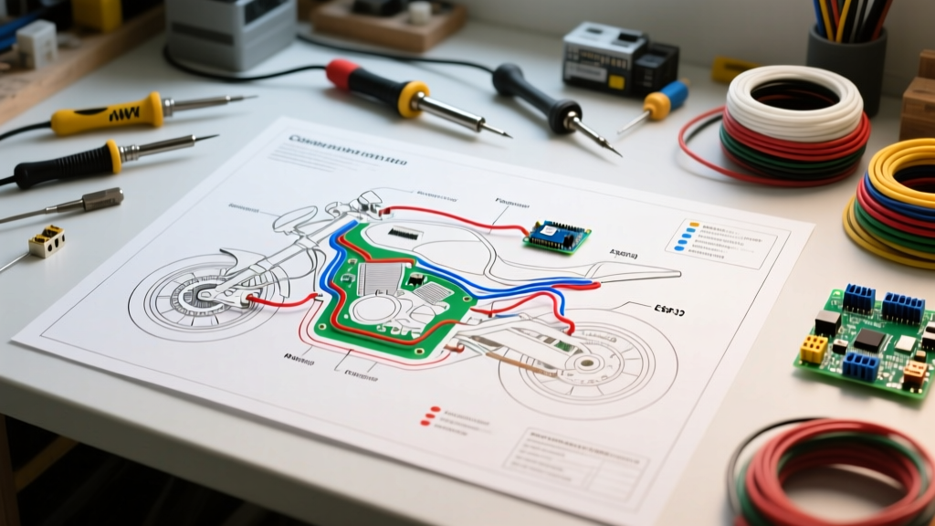
When transitioning from a stock motorcycle to a custom cafe racer, bobber, or tracker, the factory harness is often the first component to be stripped away. However, attempting to wire a motorcycle without a comprehensive plan is a recipe for catastrophic failure. Fried stators, melted insulation, and parasitic battery drains are the hallmarks of poorly planned 12V DC systems. Mastering the electrical wiring diagram of motorcycle architectures is not just about connecting positive to negative; it is an exercise in load auditing, thermal management, and spatial routing.
This installation planning guide provides a deep-dive framework for designing, sizing, and routing a custom motorcycle wiring harness in 2026, utilizing modern solid-state components and aerospace-grade materials.
Phase 1: Decoding the Diagram and Symbol Standards
Before cutting a single length of wire, you must understand the schematic language. Most OEM motorcycle diagrams adhere to either DIN 72585 (European) or JIS (Japanese Industrial Standards) formatting. When drafting your own custom diagram, standardizing your symbols is critical for future troubleshooting.
- Ground Paths: Never rely on the engine block or frame as a primary ground return path in your diagram. Custom paint, powder coating, and rubber engine mounts create high-resistance barriers. Your diagram must explicitly map dedicated 10 AWG ground straps from the engine block to the battery negative terminal, and from the frame to the battery.
- Connector Pinouts: Represent connectors as 'mating face' views. For example, a standard Sumitomo HM 090 series 4-pin connector (common on Honda/Yamaha fuel injectors) should be diagrammed from the pin-insertion side to prevent reverse-polarity wiring.
- Switch Logic: Differentiate between SPST (Single Pole Single Throw) for simple accessories and DPDT (Double Pole Double Throw) for complex routing like high/low beam headlight relays.
Phase 2: Load Auditing and Wire Gauge Selection
The most common mistake in custom motorcycle wiring is undersizing the main power feed while oversizing accessory circuits. Motorcycle electrical systems operate in a harsh, high-vibration, high-temperature environment. According to the SAE J1128 Low Tension Primary Cable Standard, automotive and motorcycle wire gauges handle different thermal loads compared to standard household NEC copper wiring.
For custom builds, you must use TXL (Thin-wall Cross-linked Polyethylene) or GXL wire. TXL offers a 125°C temperature rating and a significantly thinner outer diameter than standard PVC wire, allowing you to route more circuits through tight frame necks and steering stems.
2026 Motorcycle AWG Sizing Matrix (12V DC System)
| Wire Gauge (AWG) | Max Amperage (Chassis) | Primary Applications | Fuse Rating (Max) |
|---|---|---|---|
| 18 AWG TXL | 10A | LED Indicators, Tail Lights, Horn, ECU Sensors | 7.5A Blade |
| 16 AWG TXL | 13A | Headlights (LED), Heated Grips, Fuel Pumps | 10A Blade |
| 14 AWG TXL | 15A | Accessory Power Blocks, Cooling Fans, Reg/Rect | 15A Blade |
| 12 AWG TXL | 20A | Main Ignition Feed, Stator to Reg/Rect (AC) | 20A Blade / 25A MIDI |
| 10 AWG TXL | 30A | Main Battery Positive, Starter Solenoid, Grounds | 30A-40A MIDI/AME |
Phase 3: Power Distribution and Solid-State Integration
The era of cluttered relay blocks and dozens of mechanical fuses is over. In 2026, high-end custom builds utilize solid-state power distribution modules. The Motogadget mo.unit blue (retailing around $239) acts as a digital fuse box, relay block, and alarm system combined into a single CNC-machined aluminum billet unit.
Expert Planning Tip: When integrating a mo.unit or similar solid-state PDM (Power Distribution Module) into your wiring diagram, you must account for the 'switch side' vs. 'load side' logic. The mo.unit switches the ground path for most outputs. Your diagram must reflect that the positive feed to the headlight is constant, while the module completes the circuit via a switched ground. Reversing this will result in immediate module failure.
If you prefer a traditional analog setup, utilize a centralized fused relay block like the Painless Performance 70107 (approx. $45). This allows you to run a single heavy-gauge (10 AWG) main power feed to the block, and then branch off with smaller 14-18 AWG wires to your accessories, keeping the wiring diagram clean and logical.
Phase 4: Harness Looming, Routing, and Thermal Protection
A wiring diagram on paper does not account for the physical realities of a vibrating motorcycle frame exposed to extreme exhaust heat. Your installation plan must specify the exact looming and wrapping materials for every segment of the harness.
Material Selection Guide
- Inside the Frame/Hidden Areas: Use Tesa 51036 PET Fleece Tape. Unlike vinyl electrical tape, which turns into a sticky, melting mess when exposed to engine heat, PET fleece tape is rated for continuous temperatures up to 150°C (302°F). It is abrasion-resistant and prevents the harness from rattling inside steel frame tubes.
- Exposed Areas/Near Engine: Use Raychem DR-25 Heat Shrink or braided fiberglass sleeving. DR-25 is an elastomeric, fluoropolymer heat shrink that resists diesel, oil, and extreme heat, maintaining flexibility even in sub-zero winter riding conditions.
- Exhaust Clearances: Motorcycle headers routinely exceed 425°C (800°F). No wire insulation can survive direct contact. Your routing plan must mandate a minimum 3-inch clearance from the exhaust. If this is physically impossible, you must fabricate a thermal barrier or route the harness through the frame backbone.
Phase 5: Addressing Known Failure Modes and Edge Cases
True expertise in motorcycle electrical planning involves anticipating where OEM designs fail and engineering solutions into your custom diagram. The Electrosport Industries Tech Center frequently documents the most common charging system failures in the industry.
Edge Case 1: The 3-Phase Stator Connector Meltdown
On many vintage and modern Japanese motorcycles (e.g., Yamaha XS650, Honda CBR series), the 3-pin plastic connector between the stator and the regulator/rectifier is a notorious failure point. The stator outputs 30A+ of raw AC current. Over time, vibration and corrosion increase the resistance at the crimped pins, generating massive heat that melts the plastic housing, leading to a dead battery and a stranded rider.
The Planning Solution: Your wiring diagram must eliminate this connector entirely. Plan to cut the OEM plug off and solder the three yellow stator wires directly to the regulator/rectifier pigtail. Seal the joints using 3M MDT Adhesive-Lined Dual-Wall Heat Shrink. The inner thermoplastic adhesive melts and flows into the wire strands, creating a completely waterproof, zero-resistance bond.
Edge Case 2: LED Flasher Hyper-flashing
When upgrading from 21W halogen turn signals to 2W LED units, the OEM thermal flasher relay will interpret the low current draw as a 'blown bulb' and hyper-flash. While some diagrams suggest wiring in 50W load resistors (which generate dangerous amounts of heat and defeat the purpose of low-draw LEDs), the correct planning approach is to replace the thermal relay with an electronic solid-state LED flasher relay (e.g., CF13 JL-02) that operates independently of load amperage.
Phase 6: The Pre-Power Multimeter Checklist
Never connect the battery immediately after finishing the physical installation. Your planning guide must include a strict pre-flight testing protocol to prevent shorting out a $1,500 ECU or a custom stator.
- Continuity Testing (Power Off): Set your multimeter to the continuity (beep) setting. Place one probe on the battery negative terminal and the other on every positive feed wire in the harness. If the meter beeps, you have a dead short to ground. Do not apply power until resolved.
- Voltage Drop Testing (Cranking): Connect the battery and set the meter to DC Volts. Place probes across the main positive cable while cranking the starter. A voltage drop greater than 0.5V indicates undersized wiring or a high-resistance crimp terminal.
- AC Ripple Check (Running): With the bike running at 3,000 RPM, test the battery terminals on AC Volts. A healthy regulator/rectifier should show less than 0.5V AC. Anything higher indicates failing diodes in the rectifier, which will boil your battery acid and destroy sensitive LED drivers.
Conclusion
A meticulously planned electrical wiring diagram of motorcycle systems is the difference between a custom build that starts on the first kick and one that requires a push-start home. By adhering to SAE sizing standards, utilizing aerospace-grade TXL wire, eliminating high-resistance OEM connectors, and mapping dedicated ground paths, you ensure your motorcycle's electrical system is as reliable as its engine. For further reading on DC circuit protection standards, refer to the guidelines outlined in the NFPA 70 National Electrical Code regarding low-voltage DC applications.