
Decoding the Wiring Diagram for Grundfos Pump Systems
When installing a new hydronic heating system, domestic recirculation loop, or replacing a failed circulator, locating the correct wiring diagram for Grundfos pump models is the first step toward a reliable, code-compliant setup. Grundfos dominates the residential and light-commercial market, but their diverse lineup—ranging from the classic 3-speed UPS series to the advanced ECM-driven ALPHA2—requires distinct wiring approaches. Misinterpreting terminal layouts or ignoring PWM signal requirements can result in immediate stator burnout, voided warranties, or catastrophic control board failures.
This comprehensive appliance wiring tutorial breaks down the exact termination procedures, wire gauge requirements, and control integrations for the most common Grundfos circulators installed in 2026. Whether you are wiring a simple 115V aquastat loop or integrating a smart building management system (BMS) via PWM, this guide provides the actionable specifics you need.
Pre-Wiring Safety and NEC 2026 Compliance
Before opening the terminal box, verify the circuit is de-energized using a CAT III or CAT IV multimeter. Lockout/Tagout (LOTO) procedures are non-negotiable when working in mechanical rooms where multiple high-voltage disconnects may be present.
NEC Code Alert: Under recent updates to the National Electrical Code (NEC), GFCI protection requirements have expanded. While hardwired hydronic circulators in dedicated mechanical rooms are generally exempt from GFCI mandates under Article 210.8(D) for specific appliance receptacles, local Authorities Having Jurisdiction (AHJ) may interpret damp basement environments differently. Always confirm if your local municipality requires a GFCI breaker for 120V hardwired HVAC components.
Hardwiring the Grundfos UPS Series (UPS 15-58 & 26-99)
The UPS series remains the workhorse of the hydronic industry. However, the wiring diagram for a Grundfos pump in the UPS line varies depending on whether you are using the standard fractional horsepower models or the larger commercial variants.
Terminal Block Layout: UPS 15-58 FC (115V)
The standard UPS 15-58 FC features a simplified terminal box designed for direct line-voltage connection. Speed selection is handled manually via the rotary dial on the front of the motor housing (Settings I, II, and III), meaning the wiring diagram only requires three primary connections.
- L (Line): Connect the 115V hot wire (typically black) from your switching relay or aquastat.
- N (Neutral): Connect the neutral wire (typically white). Do not reverse L and N. While an AC motor will technically spin in the correct direction regardless of polarity, reversing them violates NEC code and creates a shock hazard during maintenance.
- G (Ground): Connect the bare copper or green equipment grounding conductor. Torque the ground screw to 0.5 Nm to prevent stripping the brass insert in the plastic housing.
External Speed Control: UPS 26-99 FC (230V)
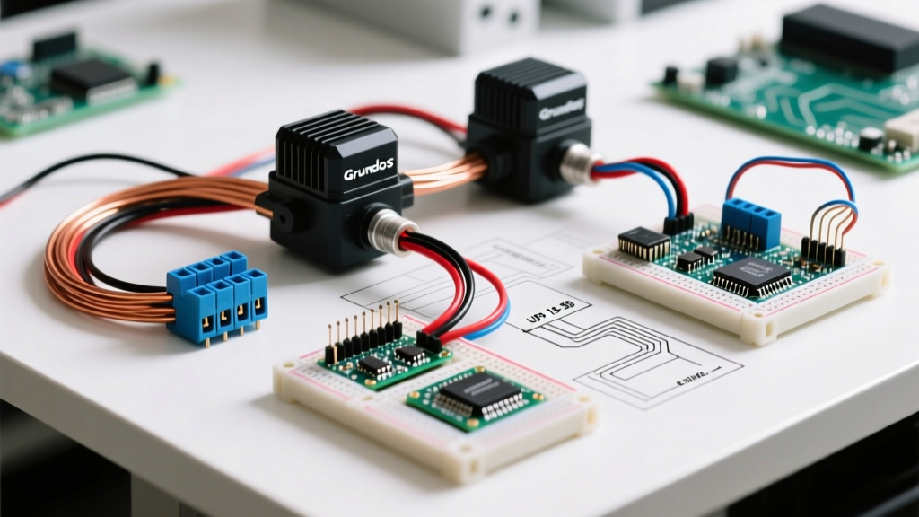
Larger models like the UPS 26-99 FC feature a more complex terminal block designed for external relay control. The wiring diagram for this Grundfos pump includes terminals for L1, L2, and L3, which correspond to High, Medium, and Low speeds. To wire this to a Taco 571-2 or Honeywell R8845 switching relay, you must route the 230V hot leg through the relay's isolated contacts to the specific speed terminal required by your system's head-loss calculation. The neutral and ground remain common.
Integrating the Grundfos ALPHA2 ECM Circulator
The ALPHA2 represents a massive shift in circulator technology, utilizing an Electronically Commutated Motor (ECM). The wiring diagram for the Grundfos ALPHA2 is deceptively simple for power, but complex for control integration.
Power Supply Wiring
The ALPHA2 features an auto-sensing power supply that accepts anywhere from 100V to 240V AC. The terminal block accepts Line, Neutral, and Ground. Because the internal inverter rectifies the AC to DC immediately, the pump is highly tolerant of minor voltage fluctuations. However, you must ensure the circuit can handle the inrush current, which is managed internally by the pump's soft-start capacitor bank.
PWM Control Signal Wiring
For advanced zoning or integration with outdoor reset controls (like the Taco iSeries or Caleffi NA550), the ALPHA2 utilizes a Pulse Width Modulation (PWM) signal. The wiring diagram for this Grundfos pump's low-voltage side requires strict adherence to signal integrity protocols:
- Cable Selection: You must use a shielded twisted-pair (STP) cable (minimum 18 AWG) for the PWM signal. Running unshielded thermostat wire parallel to 120V/240V line voltage will induce electromagnetic interference (EMI), causing the ECM motor to stutter or throw Error Code 14 (Communication Fault).
- Termination: Connect the PWM positive to the ALPHA2's designated low-voltage input terminal and the negative to the ground/common. Ensure the cable shield is grounded at the controller end only to prevent ground loops.
- Profile Selection: Use the physical button on the ALPHA2 display to set the PWM profile. Profile 2 (Constant Temperature) is the industry standard for most North American radiant floor applications.
Wire Gauge, Breaker Sizing, and Voltage Matrix
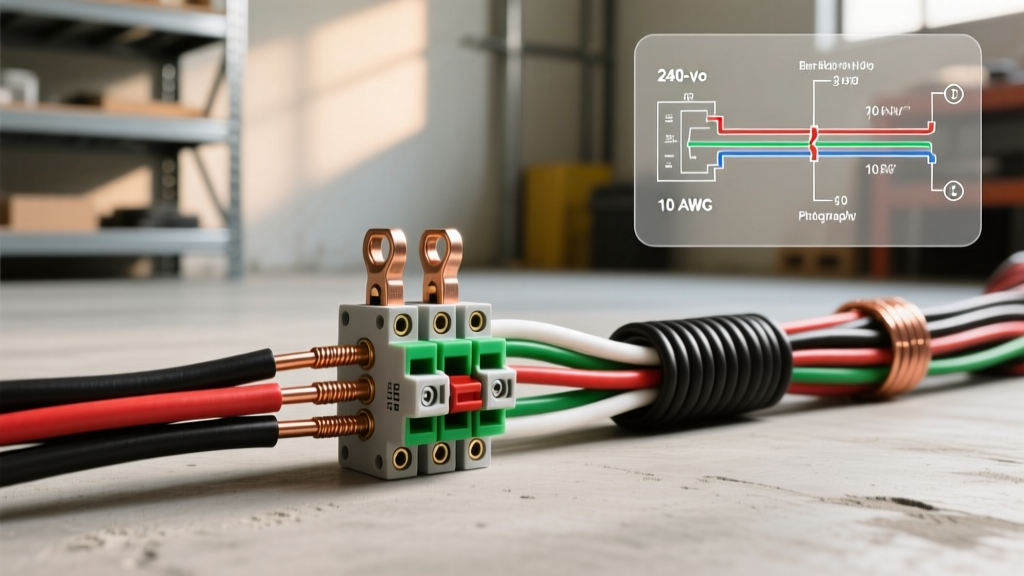
Selecting the correct wire gauge is critical to preventing voltage drop, which can cause ECM motors to overheat and standard PSC motors to lose starting torque. The Copper Development Association (CDA) provides the baseline standards for ampacity, but circulator manufacturers have specific recommendations based on run length.
| Grundfos Model | Voltage | Max FLA | Standard Wire (Up to 50ft) | Long Run Wire (50-100ft) | Breaker Size |
|---|---|---|---|---|---|
| UPS 15-58 FC | 115V AC | 0.75A | 14 AWG Cu (THHN) | 12 AWG Cu (THHN) | 15A Standard |
| UPS 26-99 FC | 230V AC | 1.50A | 14 AWG Cu (THHN) | 12 AWG Cu (THHN) | 15A 2-Pole |
| ALPHA2 15-55 | 115-230V AC | 0.45A | 14 AWG Cu (THHN) | 12 AWG Cu (THHN) | 15A Standard |
| MQ3-35 Booster | 115V AC | 8.40A | 12 AWG Cu (THHN) | 10 AWG Cu (THHN) | 15A or 20A |
Real-World Troubleshooting & Edge Cases
Even with a perfect wiring diagram for your Grundfos pump, field conditions introduce variables that cause failures. Here is how to diagnose the most common wiring-adjacent issues:
The 'Humming' Stator (Calcium Lock)
Symptom: The UPS 15-58 is wired correctly, receives 115V at the terminals, and hums loudly, but the impeller does not spin. The pump body becomes extremely hot to the touch within 10 minutes.
Diagnosis: This is rarely a wiring fault. In hard water areas, calcium carbonate builds up between the rotor and the stator can during the off-season, locking the shaft.
Fix: Disconnect power. Remove the large silver slotted screw on the front center of the motor housing. Use a flathead screwdriver to manually turn the motor shaft back and forth until it spins freely. Replace the screw and restore power.
ALPHA2 Intermittent Stuttering
Symptom: The ALPHA2 runs smoothly for hours, then randomly drops to 10% speed before surging back to 100%. The digital display shows no error codes.
Diagnosis: Electromagnetic Interference (EMI) corrupting the internal AutoAdapt sensor, or voltage sags from nearby heavy appliances (like well pumps or AC compressors) sharing the same circuit.
Fix: Verify the pump is on a dedicated 15A circuit. If the issue persists and you are using an external PWM signal, verify that the shielded cable is not routed within 6 inches of high-voltage VFD lines. Consult Grundfos Technical Support for firmware update procedures via the MI401 interface module if hardware checks pass.
Thermal Overload Tripping
Symptom: The internal thermal protection switch trips after 20 minutes of operation, shutting the pump off until it cools.
Diagnosis: Wiring a 115V pump (UPS 15-58 FC) to a 230V line. The stator windings will overheat rapidly. Alternatively, the system may be severely undersized, causing the pump to run continuously at Speed III against a closed valve (dead-heading), though Grundfos pumps are designed to tolerate dead-heading better than older cast-iron competitors.
Fix: Check line voltage at the terminal block with the circuit energized. If you read ~230V on a 115V model, the pump's internal windings are likely compromised and the unit must be replaced.
Final Commissioning Checklist
Before sealing the terminal box and insulating the pipes (if required by local energy codes), complete this final verification:
- Verify all terminal screws are torqued to 0.4 - 0.6 Nm. Loose neutrals cause arcing and melted terminal blocks.
- Ensure the cable gland (strain relief) is tightened around the outer jacket of the Romex or THHN conduit, not just the individual wires.
- For ALPHA2 models, confirm the digital display is oriented correctly and the AutoAdapt factory setting has been initialized by holding the reset button for 5 seconds upon first power-up.