
Mastering the Wiring Diagram for 12 Volt Relay Circuits
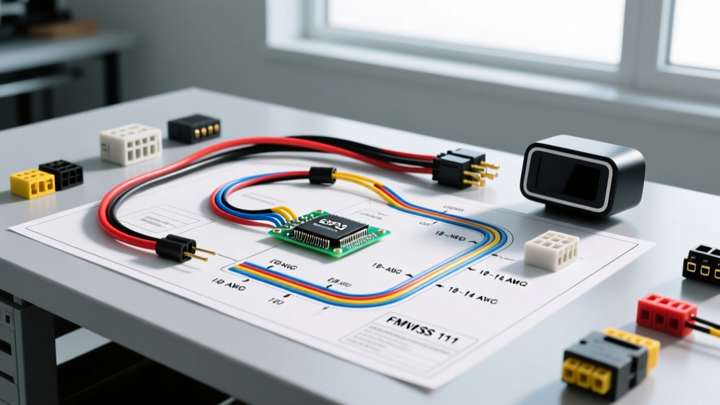
When integrating high-draw accessories into a 12V DC system—whether in automotive, marine, or off-grid solar applications—a relay is non-negotiable. A standard wiring diagram for 12 volt relay setups isolates the high-current load from the low-current switch, protecting delicate OEM wiring and control modules. However, simply following a basic schematic is not enough. The longevity and safety of your circuit depend entirely on proper wire gauge selection and adherence to standardized DC color codes.
In this comprehensive guide, we break down the exact pinout configurations, calculate voltage drop for precise American Wire Gauge (AWG) selection, and outline the industry-standard color codes expected by professional installers in 2026.
Understanding the Standard 12V Relay Pinout (DIN 72552)
Most 12V automotive and marine applications utilize the standard ISO 7588 (often referred to as Bosch-style) relay. These are typically rated for 30A to 40A and follow the DIN 72552 numbering standard. Before running any wire, you must understand the terminal designations:
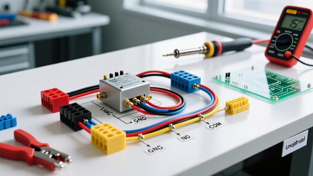
- Pins 85 & 86 (The Coil): These are the low-current trigger terminals. One receives 12V from your switch or ECU, and the other connects to ground. Polarity generally does not matter for standard electromechanical relays, but it is critical if your relay has an internal suppression diode.
- Pin 30 (Common Input): The high-current power source. This connects directly to the battery positive terminal via an appropriately sized fuse.
- Pin 87 (Normally Open - NO): The high-current output that powers your accessory when the relay is energized.
- Pin 87a (Normally Closed - NC): Present only on 5-pin relays. This outputs power when the relay is off and cuts power when the relay is on. (Often left unused in standard accessory wiring).
Wire Gauge Selection: Matching AWG to Amperage and Distance
The most common failure point in DIY 12V wiring is undersized cabling on the high-current side (Pins 30 and 87). In a 12V system, voltage drop is a severe limitation. A mere 3% voltage drop at 12V equals 0.36V, which can cause accessories like LED light bars or winch solenoids to malfunction or overheat.
According to the Blue Sea Systems Circuit Calculator, wire gauge must be selected based on both the maximum amperage and the total round-trip length of the wire (positive + negative).
12V DC Wire Gauge Chart (3% Voltage Drop Limit)
| Load Current (Amps) | Max Length (10 AWG) | Max Length (12 AWG) | Max Length (14 AWG) | Recommended Fuse |
|---|---|---|---|---|
| 10A | 45 ft | 25 ft | 15 ft | 15A |
| 15A | 30 ft | 15 ft | 10 ft | 20A |
| 20A | 20 ft | 10 ft | 5 ft | 25A |
| 30A | 15 ft | 5 ft | Not Recommended | 35A or 40A |
| 40A | 10 ft | Not Recommended | Not Recommended | 50A |
Expert Warning: Never use Copper Clad Aluminum (CCA) wire for 12V relay circuits. CCA wire has roughly 40% higher electrical resistance than pure copper and is highly susceptible to galvanic corrosion when crimped with standard copper terminals. Always specify SAE J1128 GXL or TXL cross-linked polyethylene pure copper wire for engine bay and marine environments.
Standard Automotive DC Color Code Reference
While the NFPA 70 National Electrical Code (NEC) governs AC building wiring, 12V DC automotive and marine wiring relies on SAE and ABYC (American Boat and Yacht Council) color conventions. Adhering to these colors ensures that any technician can troubleshoot your wiring diagram for 12 volt relay setups years down the line.
High-Current Load Circuit (Pins 30 & 87)
- Red: Battery positive (+) to Pin 30. Must be fused within 18 inches of the battery.
- Yellow or Blue: Pin 87 to the accessory positive (+). Yellow is typically used for high-amp continuous loads (like inverters or fridges), while blue is common for lighting.
- Black: Accessory negative (-) to chassis ground or negative busbar.
Low-Current Trigger Circuit (Pins 85 & 86)
- White or Light Blue: Switched 12V+ from the dash switch, ignition source, or ECU to Pin 86.
- Black: Pin 85 to chassis ground. (Note: Use 16 AWG or 18 AWG for the coil ground; it carries less than 0.2A).
Step-by-Step: Wiring a 12V 40A Relay for an Off-Road Light Bar
Let us apply this knowledge to a real-world scenario. You are installing a 120W LED light bar (drawing 10A at 12V) using a standard Omron G8V series 40A automotive relay. The total round-trip wire distance from the battery to the relay, to the light bar, and back to ground is 20 feet.
- Size the Load Wire: For a 10A load over 20 feet, 14 AWG is sufficient according to our chart, but upgrading to 12 AWG GXL wire provides a safer margin and better physical durability. Cost: ~$0.65 per foot.
- Run the Power Feed (Pin 30): Run 12 AWG Red wire from the battery positive to Pin 30. Install a 15A MAXI fuse in an inline waterproof holder within 12 inches of the battery terminal.
- Run the Load Output (Pin 87): Run 12 AWG Blue wire from Pin 87 to the positive pigtail of the LED light bar.
- Ground the Accessory: Run 12 AWG Black wire from the light bar negative to a clean, bare-metal chassis ground point. Use a star washer to bite through the paint.
- Wire the Coil (Pins 85 & 86): Run 16 AWG White wire from a cabin toggle switch (fed by an ignition-switched fuse) to Pin 86. Run 16 AWG Black wire from Pin 85 to a local chassis ground.
- Install a Flyback Diode: Solder a 1N4007 rectifier diode across Pins 85 and 86, with the silver stripe (cathode) facing Pin 86. This is critical to absorb the inductive voltage spike when the relay coil de-energizes, protecting your dashboard toggle switch or ECU from arcing and failure.
Common Failure Modes and Troubleshooting
Even with a perfect wiring diagram for 12 volt relay configurations, environmental factors and edge cases can cause failures. Here is what to look for when a circuit fails:
1. Relay Chattering or Clicking Rapidly
Cause: Severe voltage drop on the trigger circuit (Pins 85/86). When the relay engages, it draws a brief inrush current to magnetize the coil. If the trigger wire is too long or undersized (e.g., using 20 AWG wire for a 15-foot dash switch run), the voltage at the coil drops below the 9V minimum hold threshold. The relay drops out, voltage recovers, and it pulls in again rapidly.
Fix: Upgrade the trigger wire to 14 AWG or run a dedicated 12V+ feed to the switch rather than tapping into a high-resistance OEM sense wire.
2. Melted Relay Socket or Terminals
Cause: High resistance at the crimp connections or using cheap, stamped-brass relay sockets instead of ceramic or high-temp nylon sockets with nickel-plated terminals. In 2026, aftermarket relay harnesses using CCA wire and thin steel spade terminals are notorious for melting under continuous 30A loads.
Fix: Use ratcheting crimpers (like the Titan 11200) to ensure cold-weld crimps on the terminals, and always apply dielectric grease (like MG Chemicals 846) to the spade connections to prevent oxidation.
3. Accessory Remains On After Switch is Turned Off
Cause: The relay contacts (Pins 30 and 87) have physically welded together due to arcing from a highly capacitive or inductive load (like a winch motor or large compressor) lacking a pre-charge circuit or snubber.
Fix: Replace the relay with a solid-state relay (SSR) rated for DC inductive loads, or add an RC snubber network across the load terminals.
Frequently Asked Questions (FAQ)
Can I use a 5-pin relay in place of a 4-pin relay?
Yes. A 5-pin relay simply includes the 87a (Normally Closed) terminal. If your wiring diagram for 12 volt relay setups only requires a standard Normally Open (NO) circuit, you can simply leave the 87a pin empty and unconnected. It will function identically to a 4-pin relay.
Does the coil ground (Pin 85) need to be as thick as the load ground?
No. The electromagnetic coil inside a standard 12V relay typically draws between 120mA and 180mA. A 16 AWG or even 18 AWG wire is more than sufficient for the coil ground, provided the physical length is under 10 feet. The heavy-gauge grounding is strictly reserved for the accessory load circuit.
Why is my relay getting hot to the touch?
It is normal for the plastic casing of a 12V relay to reach 140°F (60°C) during continuous operation due to the resistance of the copper coil windings. However, if the metal spade terminals are too hot to touch, you have a high-resistance connection caused by a poor crimp, undersized wire, or oxidized socket terminals.