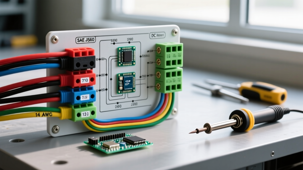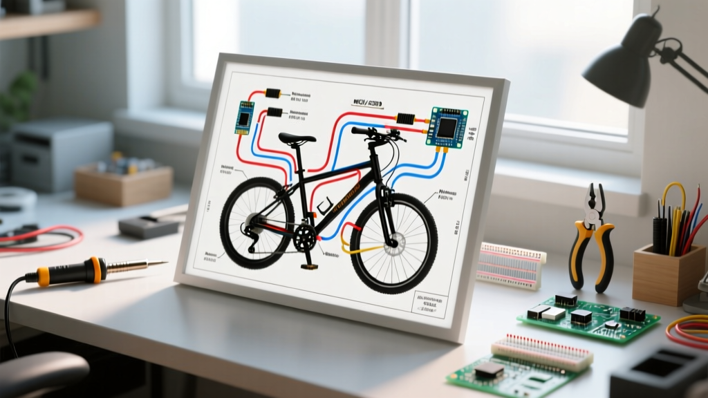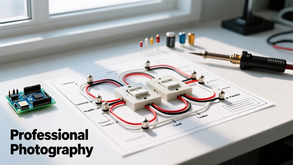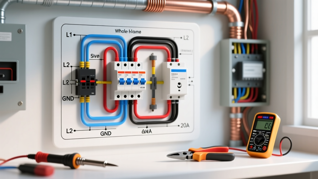

Understanding the Anatomy of a Starter Motor Circuit
Executing a flawless wiring diagram for starter motor installations is the difference between reliable, instant cranking and being stranded with a clicking solenoid. In 2026, the automotive aftermarket has heavily shifted toward high-torque, gear-reduction mini starters (like the popular Denso-style or Powermaster UltraTorq series). While these units draw less peak amperage than the heavy, direct-drive OEM starters of the past—typically 150 to 180 amps versus 250+ amps—they demand incredibly clean trigger signals, especially when integrated with modern EFI systems and sensitive ECUs.
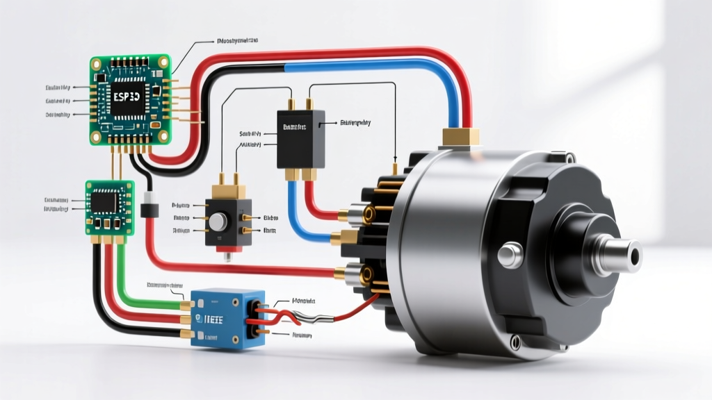
Before cutting a single wire, you must understand the core terminals on a standard starter solenoid:
- B+ (Battery) Terminal: The large threaded post receiving main battery voltage.
- M (Motor) Terminal: The large threaded post connecting directly to the starter motor's internal windings via a heavy copper strap.
- S (Start/Trigger) Terminal: The small spade or threaded post that receives the 12V ignition signal to engage the solenoid plunger.
- R (Resistance/Bypass) Terminal: Found mostly on classic points-style ignitions to provide a 12V boost to the coil during cranking. (Largely obsolete on modern HEI or EFI setups).
Selecting the Correct Wire Gauge and Terminals
A common failure point in DIY starter wiring is undersizing the main power cable. According to the SAE J1128 standard for automotive low-tension primary cable, wire gauge must be selected based on both the maximum amperage draw and the total length of the cable run. In 2026, pure copper (SAE J1128 Type SGT) battery cable costs roughly $4.50 to $6.00 per foot, making it a worthwhile investment over cheaper Copper-Clad Aluminum (CCA) alternatives that suffer from severe voltage drop.
Main Power Cable Sizing Matrix
| Cable Run Distance | Starter Draw (Up to 200A) | Starter Draw (200A - 300A) |
|---|---|---|
| Under 10 Feet | 1 AWG | 1/0 AWG (One-Aught) |
| 10 to 15 Feet | 1/0 AWG | 2/0 AWG (Two-Aught) |
| Over 15 Feet (e.g., Rear Battery) | 2/0 AWG | 3/0 AWG or 4/0 AWG |
Pro-Tip: Always use adhesive-lined, dual-wall heat shrink ring terminals (3/8-inch stud size for most standard solenoids) and crimp them with a hex-indent hydraulic crimper, not a simple hammer-crimp tool.
Step-by-Step Walkthrough: Executing the Wiring Diagram
Follow this precise sequence to wire a starter motor utilizing a Bosch-style 4-pin relay. Using a relay is highly recommended to prevent voltage drop from the ignition switch to the solenoid's S terminal.
Step 1: Safety Isolation and Chassis Prep
Disconnect the negative battery terminal. Locate the chassis ground point nearest to the starter motor. Use a wire wheel to strip away paint, rust, and undercoating down to bare, shiny metal. A poor engine-to-chassis ground is the number one cause of 'slow crank' symptoms, often misdiagnosed as a bad starter.
Step 2: Routing the Main Power Cable
Route your 1/0 AWG positive cable from the battery's positive terminal to the starter solenoid's B+ terminal. Secure the cable every 12 inches using UV-resistant nylon cable ties. Keep the cable at least 3 inches away from exhaust headers. If routing near exhaust is unavoidable, sleeve the cable in a fiberglass heat-shield wrap rated for 1,200°F.
Step 3: Wiring the Starter Relay (Control Circuit)
Mount a heavy-duty 4-pin relay (rated for at least 40A continuous, such as the Bosch 0332014150) in the engine bay, away from excessive heat.
- Pin 30 (Power In): Connect a short 10 AWG pigtail with a ring terminal directly to the starter's B+ terminal or a nearby 150A mega-fuse distribution block.
- Pin 87 (Power Out): Run a 10 AWG wire from this pin directly to the starter solenoid's S (Trigger) terminal.
- Pin 85 (Ground): Connect to a clean, bare-metal chassis ground using a ring terminal and star washer.
- Pin 86 (Ignition Trigger): Run a 12 AWG wire from this pin to the 'Start' (crank) position terminal on your ignition switch.
Step 4: Establishing the Engine Ground
Run a dedicated 1/0 AWG ground cable from the battery's negative terminal directly to a threaded boss on the engine block or cylinder head. Do not rely solely on the engine mounts for grounding, as rubber isolators and engine torque movement can break continuity.
OEM vs. High-Torque Mini Starter: Wiring Differences
When upgrading from a heavy OEM direct-drive starter to a modern gear-reduction mini starter, the wiring diagram requires slight modifications to ensure longevity and prevent 'run-on' (where the starter stays engaged after the key is released).
| Feature | OEM Direct-Drive Starter | Aftermarket Gear-Reduction Mini Starter |
|---|---|---|
| Peak Amperage Draw | 220A - 300A+ | 140A - 180A |
| Required Main Cable | 1/0 AWG or 2/0 AWG mandatory | 1 AWG or 1/0 AWG sufficient |
| Heat Sensitivity | Moderate (heavy copper mass) | High (compact housing, requires heat shield) |
| Run-On Risk | Low | High (requires diode protection on EFI cars) |
Advanced Troubleshooting: Voltage Drop and Heat Soak
Even with a perfect wiring diagram for starter motor execution, environmental factors can degrade performance. According to diagnostic guidelines from Hella Techworld, testing the circuit under load is the only way to verify integrity.
The Voltage Drop Test
Set your digital multimeter to DC Volts. Place the positive probe on the battery's positive post and the negative probe on the starter's B+ terminal. Have an assistant crank the engine. A reading above 0.5V indicates excessive resistance in the positive cable or crimps. Repeat on the ground side (battery negative post to engine block). A ground-side drop over 0.2V requires cleaning or replacing the ground cable. For deeper multimeter techniques, refer to Fluke's guide on voltage drop testing.
Curing Heat Soak and Run-On
Mini starters mounted close to exhaust headers often suffer from 'heat soak,' where internal solenoid resistance spikes due to ambient heat, preventing engagement. Install a starter heat shield blanket. Furthermore, if your starter stays engaged for a split second after releasing the key (run-on), the alternator or ignition system is back-feeding voltage into the S terminal. The permanent fix is soldering a 1N5400 series blocking diode or a dedicated MSD solenoid diode across the S and M terminals, allowing current to flow only toward the solenoid.
Expert Insight: Never use the starter solenoid's S terminal to trigger a high-draw fuel pump relay. The S terminal is designed only to pull the solenoid plunger. Back-feeding heavy loads into the trigger circuit will fry your ignition switch and melt 12 AWG trigger wires.