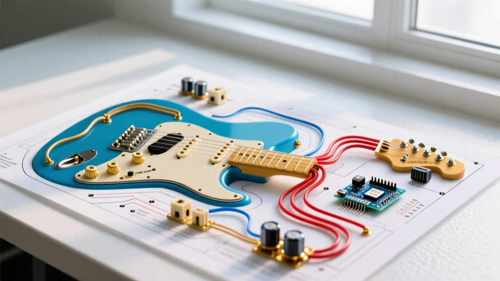

Pre-Installation Audit: Mapping Your Telecaster Circuit
Planning a rewire for a Fender Telecaster requires more than just glancing at a basic schematic and firing up a soldering iron. A successful installation hinges on component synergy, proper grounding topology, and meticulous workspace preparation. Whether you are restoring a vintage 1968 Thinline or upgrading a modern Player Series, understanding the electrical architecture of the Telecaster is critical. In 2026, with the rising cost of boutique pickups and premium hardware, executing a flawless installation on the first attempt is essential to preserve your investment and your instrument's tonal integrity.
Before cutting any wire, you must decide on your target topology. The standard Telecaster circuit is deceptively simple, but minor variations drastically alter the high-frequency response and taper of your controls.
Standard Vintage vs. Modern Topologies
The traditional 'Vintage' Telecaster wiring routes the tone capacitor between the volume switch lug and the tone potentiometer. This setup, while iconic, can cause a slight high-frequency loss even when the tone knob is set to 10, due to the capacitive load interacting with the circuit's impedance. The 'Modern' topology, widely adopted by Fender in the late 1970s and standard on most current production models, routes the capacitor from the tone pot's wiper (middle lug) to ground. This modern approach isolates the cap from the signal path when the knob is at 10, yielding a noticeably brighter and more articulate full-open tone.
Component Selection Matrix: The Bill of Materials
Cheap potentiometers and switches are the primary culprits behind scratchy controls, signal degradation, and mechanical failure. When planning your installation, allocate your budget toward mil-spec or premium audio-grade components. Below is the recommended Bill of Materials (BOM) for a professional-grade Telecaster rewire, reflecting current 2026 market pricing.
| Component | Specification | Purpose & Notes | Est. Cost |
|---|---|---|---|
| Volume Pot | CTS 450G Series 250K Audio Taper | Provides a smooth, musical volume swell. Split shaft for knurled knobs. | $8.50 |
| Tone Pot | CTS 450G Series 250K Audio Taper | Audio taper prevents the 'all-or-nothing' tone drop-off common with linear pots. | $8.50 |
| Selector Switch | CRL 3-Way Lever Switch (Spring Return) | USA-made, heavy-duty contacts. Superior to imported Oak Grigsby clones. | $14.00 |
| Tone Capacitor | Sprague Orange Drop 715P 0.047uF | Delivers the classic, warm Telecaster rolled-off tone. Use 0.022uF for brighter pickups. | $4.50 |
| Output Jack | Switchcraft #11 Mono Jack | Heavy-duty nickel contacts. Avoid cheap open-frame jacks that lose tension. | $5.00 |
| Hookup Wire | 22 AWG Stranded Tinned Copper | PVC insulation for tight routing, or cloth push-back for vintage aesthetics. | $12.00 |
The Master Wiring Diagram for Telecaster: Node-by-Node Execution
Translating a visual wiring diagram for a Telecaster into physical execution requires a systematic approach. Orient all potentiometers with the shafts facing down and the lugs facing up. Number the lugs 1, 2, and 3 from left to right. For the CRL 3-way switch, orient it with the spring mechanism facing away from you; the left side is Stage A, the right side is Stage B.
Volume Potentiometer Routing
- Lug 1: Connect to the common output lug of the CRL switch (Stage B, bottom lug).
- Lug 2 (Wiper): Connect to the Tip lug of the Switchcraft #11 output jack. This is your main audio out.
- Lug 3: Connect to ground. Solder a short jumper to the back casing of the volume pot, and run the main ground wire from the output jack sleeve here.
Tone Potentiometer Routing (Modern Topology)
- Lug 1: Connect to the volume input (Stage B, bottom lug of the CRL switch) alongside the wire going to Volume Lug 1. This ensures the tone circuit receives signal in all switch positions.
- Lug 2 (Wiper): Connect to one leg of the 0.047uF tone capacitor.
- Lug 3: Left empty (or bent back and grounded, though modern wiring leaves it floating to prevent unintended loading).
- Capacitor Ground: The second leg of the tone capacitor solders to the back casing of the tone pot.
CRL 3-Way Switch Mapping
- Stage A (Top Left): Bridge pickup hot lead.
- Stage A (Middle Left): Jumper to Stage B (Middle Right).
- Stage A (Bottom Left): Ground (if using a 4-way switch mod, otherwise empty in standard 3-way).
- Stage B (Top Right): Neck pickup hot lead.
- Stage B (Middle Right): Jumper from Stage A Middle.
- Stage B (Bottom Right): Common output to Volume Lug 1.
Workspace Preparation and Tooling Specifics
A proper installation requires precise thermal management. Potentiometer casings act as massive heat sinks. If your iron lacks the thermal recovery to melt solder quickly, you will create a 'cold joint' or, worse, overheat the pot and melt the internal phenolic track, permanently ruining an $8.50 CTS component.
Expert Soldering Protocol: Use a temperature-controlled station like the Hakko FX-888D or Weller WE1010NA. Set the tip temperature to 360°C (680°F) when soldering to pot casings and switch lugs, and drop to 320°C (608°F) for delicate pickup leads. Always use 60/40 Sn/Pb rosin-core solder in a 0.031-inch diameter for optimal flow and capillary action.
Before applying the iron, always 'tin' both the wire and the lug. Apply a small dab of solder to the stripped wire end, and a small pool to the lug or pot casing. When joining them, the pre-tinned surfaces will fuse instantly, requiring less than two seconds of heat application. For authoritative guidance on soldering techniques and joint inspection, refer to the StewMac Understanding Guitar Wiring guide, which remains an industry standard for luthiers and techs.
Grounding Strategy: Eliminating 60-Cycle Hum
The Telecaster's single-coil pickups are notoriously susceptible to electromagnetic interference (EMI) and 60-cycle hum. A flawless wiring diagram is useless if your grounding topology is flawed. Avoid 'daisy-chaining' grounds from the neck pickup to the bridge, then to the pots, as this creates ground loops that act as antennas for radio frequency interference (RFI).
Implementing Star Grounding
Adopt a 'Star Grounding' methodology. Designate the back casing of the volume potentiometer as the central ground hub. Run individual, dedicated ground wires from every component directly to this central hub:
- Output jack sleeve.
- Neck pickup negative lead.
- Bridge pickup negative lead (and the metal bridge plate via a stripped wire end sandwiched under the plate screws).
- Tone pot casing (via a short jumper).
- CRL switch mounting screws (via a lug ring).
Furthermore, line the control cavity and the underside of the pickguard with 0.0015-inch copper foil tape featuring conductive adhesive. Ensure all overlapping seams are continuous, and run a dedicated ground wire from the copper shielding to your central star ground. This creates a Faraday cage that drastically reduces high-frequency hash and fluorescent light hum.
Pre-Flight Troubleshooting and Edge Cases
Never restring and plug into a high-gain amplifier without conducting a pre-flight continuity audit. Use a digital multimeter set to the continuity (beep) mode to verify your connections against a trusted schematic, such as those provided in the Seymour Duncan Wiring Diagrams database.
Common Failure Modes to Inspect
- Pot Casing Shorts: If you bend the tone pot's Lug 3 back to touch the casing, ensure it doesn't accidentally short against the copper shielding tape or the steel control plate. Use a piece of heat-shrink tubing or Kapton tape to insulate the wiper and unused lugs.
- Switch Lug Bridging: The CRL switch lugs are spaced closely. Excess solder can easily bridge Stage A and Stage B, causing the bridge and neck pickups to fire simultaneously in the middle position, resulting in a thin, out-of-phase sound if the pickups are not reverse-wound/reverse-polarity (RWRP).
- Output Jack Wiring Reversal: The Switchcraft #11 jack has a Tip (hot) and a Sleeve (ground). The Tip is the shorter, inner lug. The Sleeve is the longer, outer lug that touches the plug's barrel. Reversing these will ground your signal and send hum through the amplifier chassis.
By treating your Telecaster rewire as a structured engineering project rather than a casual craft, you ensure a noise-free, highly responsive instrument that honors the legacy of Leo Fender's original design while leveraging modern component reliability.