
Decoding the Wiring Diagram for Onan Generator Output Terminals
Integrating a Cummins Onan generator into your home standby system or RV electrical panel requires more than just connecting heavy-gauge wires to a breaker. The specific wiring diagram for Onan generator models dictates how the alternator output interfaces with your transfer switch, main distribution panel, and grounding system. Whether you are wiring an Onan RV QG 4000 for a 50-amp coach or an Onan 20ES for a 20kW home standby application, misinterpreting the control board pinouts or AC output terminals can result in catastrophic backfeeding, voided warranties, or severe fire hazards.
As of the 2026 National Electrical Code (NEC) updates, generator integration demands strict adherence to neutral bonding rules and arc-fault protection standards. This guide breaks down the panel and breaker integration process, providing actionable wire gauge matrices, torque specifications, and troubleshooting frameworks for certified electricians and advanced DIYers.
Core Architecture: Generator Output to Transfer Switch
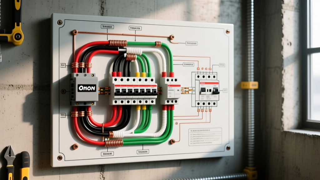
Before touching a breaker, you must understand the pathway of the current. The wiring diagram for Onan generator systems typically routes the AC output from the generator's stator windings through an internal circuit breaker (on RV models) or directly to an external junction box (on standby models). From there, the conductors travel to an Automatic Transfer Switch (ATS) or a Manual Transfer Switch (MTS) before reaching the main load center.
Identifying the Terminals
- L1 and L2 (Hot Legs): On 120/240V models like the Onan 20ES, L1 and L2 carry the 240V split-phase load. On 120V-only models like the QG 4000, L1 is the single hot leg, and L2 may be absent or used as a neutral passthrough depending on the exact harness.
- N (Neutral): The current-carrying grounded conductor. This is the most critical wire in your wiring diagram, as its bonding status dictates your transfer switch type.
- G or E (Ground): The equipment grounding conductor (EGC), which must remain continuous and unswitched from the generator frame to the main panel's ground bus.
Critical Panel & Breaker Sizing Matrix
Selecting the correct breaker and wire gauge is non-negotiable. Undersized breakers will nuisance-trip during motor startups (like HVAC compressors), while oversized breakers fail to protect the alternator windings from thermal overload. Below is the definitive sizing matrix for popular Onan models based on continuous load calculations and THHN/THWN-2 copper conductors in conduit.
| Onan Model Series | Max Output (kW) | Voltage / Phase | Max Amps | Required Breaker Size | Min. Copper Wire Gauge (THHN) |
|---|---|---|---|---|---|
| QG 4000 (RV) | 4.0 kW | 120V / 1-Phase | 33.3A | 40A (1-Pole) | #8 AWG |
| QG 5500 (RV) | 5.5 kW | 120V / 1-Phase | 45.8A | 50A (1-Pole) | #6 AWG |
| RS 12000 (Standby) | 12.0 kW | 120/240V / 1-Phase | 50.0A | 60A (2-Pole) | #6 AWG |
| 20ES (Standby) | 20.0 kW | 120/240V / 1-Phase | 83.3A | 100A (2-Pole) | #3 AWG |
Note: If your conduit run exceeds 100 feet from the generator to the transfer switch, you must apply NEC Article 310 voltage drop calculations and upsize the wire by at least one gauge to maintain a maximum 3% voltage drop.
The Neutral Bonding Dilemma: 2-Pole vs. 3-Pole Transfer Switches
The most common point of failure when interpreting a wiring diagram for Onan generator setups is misunderstanding the neutral-to-ground bond. According to NFPA 70 (NEC) Article 250, a premises wiring system must have exactly one neutral-to-ground bond.
Scenario A: Bonded Neutral Generators (Typical RV & Portable)
Many Onan RV generators (like the QG series) feature a bonded neutral internally at the alternator housing. If you connect this to a standard 2-pole transfer switch (which only switches the hot legs), you create a parallel neutral path back to the main utility panel's bond. This causes stray current on the ground wire and will instantly trip GFCI/AFCI breakers. Solution: You must use a 3-pole transfer switch that switches the neutral, or physically remove the neutral bonding strap inside the Onan generator's junction box (converting it to a floating neutral, which requires labeling and adherence to local codes).
Scenario B: Floating Neutral Generators (Typical Home Standby)
Larger home standby units like the Onan 20ES are typically shipped with a floating neutral (the neutral is isolated from the generator frame). In this case, the neutral is bonded at the main utility panel. Solution: A standard 2-pole transfer switch is perfectly safe and code-compliant, as the neutral passes straight through without creating a secondary bond.
Step-by-Step Breaker Panel Integration
Follow this sequence to ensure a safe, code-compliant connection between your Onan generator and your home's distribution panel via an ATS (such as the ASCO 300 Series or Reliance Controls RX series, which typically retail between $550 and $850 in 2026).
- Disconnect All Power: Shut off the main utility breaker and disconnect the generator's start battery to prevent accidental auto-starts during wiring.
- Route the Conduit: Run liquid-tight flexible metallic conduit (LFMC) or rigid PVC from the generator's external junction box to the ATS. Maintain a minimum 6-inch clearance from low-voltage signal wires.
- Pull the Conductors: Pull L1, L2, Neutral, and Ground. Use color-coding strictly: Black (L1), Red (L2), White (Neutral), Green (Ground).
- Terminate at the Generator: Connect to the Onan output lugs. Apply exactly 45 in-lbs of torque to the neutral bus bar and 50 in-lbs to the hot lugs (verify against your specific model's installation manual).
- Terminate at the ATS: Connect the generator inputs to the "Emergency" or "Generator" side of the ATS. Ensure the utility lines are on the "Normal" side.
- Route to the Subpanel/Main Panel: Connect the ATS load side to your designated breaker panel.
- Verify the Control Harness: The wiring diagram for Onan generator ATS setups includes a 2-wire or 4-wire low-voltage control harness (usually 18 AWG shielded) that signals the generator to start upon utility loss. Keep this shielded wire separated from AC lines to prevent electromagnetic interference (EMI).
Troubleshooting Voltage Drops and GFCI Nuisance Trips
Even with a perfect wiring diagram, real-world conditions introduce variables. Here is how to diagnose the two most common Onan integration failures.
1. GFCI Breakers Tripping Under Load
If your kitchen or bathroom GFCI breakers trip the moment the ATS switches to generator power, you almost certainly have a multiple-bond issue. Use a clamp meter to measure current on the equipment grounding conductor (EGC) while the generator is running. If you read anything above 0.5A on the ground wire, neutral current is bleeding onto the ground path. Re-verify your transfer switch pole configuration and ensure the generator's internal bond matches your ATS switching logic.
2. Onan Fault Code 14 (Undervoltage) or Code 13 (Overvoltage)
When the generator control board detects voltage outside the 108V-132V window, it will shut down to protect connected appliances. If your wiring diagram is correct but you are throwing Code 14, check for loose neutral connections at the ATS. A high-resistance neutral connection will cause L1 to sag (undervoltage) while L2 spikes (overvoltage) on a 240V system. Torque all neutral lugs to manufacturer specifications and inspect for oxidation on aluminum wire pigtails.
Expert Warning: Never attempt to backfeed a main panel using a "suicide cord" (a male-to-male plug) without a certified interlock kit or transfer switch. Not only is this a severe electrocution hazard for utility line workers, but modern Onan inverter and AVR systems will actively fault and disable the alternator if they detect an out-of-phase grid backfeed. Always refer to the official Cummins Onan power generation documentation for model-specific interlock requirements.
Final Commissioning and Load Testing
Once the physical wiring is complete, commissioning the system ensures the wiring diagram for Onan generator components translates to reliable real-world performance. Start the generator manually and allow it to warm up for 3 minutes. Using a true-RMS digital multimeter, measure L1-to-Neutral and L2-to-Neutral at the ATS load terminals; both should read between 118V and 124V.
Next, simulate a utility failure by turning off the main utility breaker. The ATS should detect the voltage drop, signal the Onan control board via the low-voltage harness, and switch to generator power within 10 to 15 seconds. Apply your planned continuous load (typically 80% of the generator's max rated wattage) and monitor the voltage for 30 minutes. If the voltage remains stable and the breaker panel shows no signs of thermal heating (verify with an infrared thermometer), your panel integration is complete, safe, and ready for the next grid outage.