
Introduction to Electric Strike Access Control
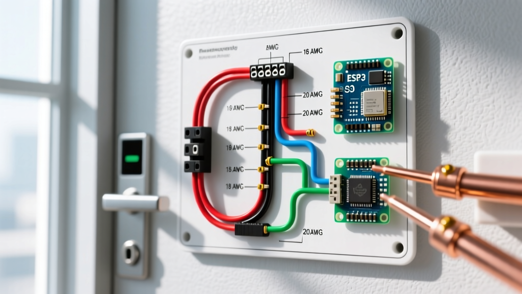
Integrating an electric strike into a commercial or high-security residential door requires more than just running two wires to a solenoid. A proper electric strike wiring diagram must account for life safety codes, voltage drop over long wire runs, back-EMF protection, and the mechanical realities of door preload. As of 2026, with the widespread adoption of PoE (Power over Ethernet) access control panels like the HID VertX EVO and LenelS2 NetBox, understanding how to interface low-voltage dry contacts with high-current locking hardware is a critical skill for electrical and security integrators.
This guide breaks down the exact wiring topologies for the two primary modes of operation: fail-secure and fail-safe. We will use industry-standard hardware references, such as the HES 1006 heavy-duty strike and the Altronix AL400ULX power supply, to provide actionable, real-world wiring instructions.
Fail-Safe vs. Fail-Secure: Choosing the Right Mode
Before pulling any wire, you must determine the operational mode required by the door's function and local fire codes. The wiring topology changes entirely based on this choice.
Fail-Secure (Default Locked)
In a fail-secure setup, the strike remains locked when power is removed. It only unlocks when voltage is applied to the solenoid. This is the standard for exterior perimeter doors where security must be maintained during a power outage. Fail-secure strikes utilize a Normally Open (NO) relay circuit.
Fail-Safe (Default Unlocked)
In a fail-safe setup, the strike remains unlocked when power is removed. It requires continuous voltage to stay locked. This is mandatory for stairwell doors and primary egress routes to ensure occupants can escape during a fire or power failure. Fail-safe strikes utilize a Normally Closed (NC) relay circuit.
Life Safety Code Warning: According to NFPA 101 (Life Safety Code) and OSHA 1910.36, fail-secure electric strikes are strictly prohibited on doors serving as a required means of egress unless they are equipped with a mechanical fail-safe egress mechanism (like a panic bar) that retracts the strike keeper independently of the electrical circuit. Always consult NFPA 80 for fire-rated door assembly restrictions.
Core Components of an Electric Strike Circuit
A robust access control circuit consists of four main nodes:
- Power Supply: A regulated, access-control-grade power supply (e.g., Altronix AL400ULX, approx. $130). Do not use standard LED drivers or wall warts; they lack the surge capacity to handle the inrush current of a solenoid coil.
- Access Control Relay: The dry contact output from your access control board or a standalone keypad.
- The Electric Strike: The physical hardware (e.g., HES 9600 series, approx. $280).
- Protection Components: Diodes or Metal Oxide Varistors (MOVs) to protect the relay.
Power Supply Sizing and Voltage Drop
Electric strikes draw significant inrush current. A 12VDC strike might draw 0.5A continuously but spike to 1.2A for the first 50 milliseconds upon activation. If your wire gauge is too thin, the voltage at the strike will drop below the 10.5V minimum threshold, resulting in a buzzing strike that fails to release the latch.
Wire Gauge vs. Distance Chart (12VDC / 24VDC)
Use the following matrix to select the correct copper wire gauge based on the total loop distance (distance from power supply to strike, multiplied by two). This assumes a standard 0.5A draw at 12VDC or 0.25A at 24VDC.
| Wire Gauge (AWG) | Max Distance 12VDC (0.5A) | Max Distance 24VDC (0.25A) | Resistance per 1000ft |
|---|---|---|---|
| 18 AWG | 150 feet | 300 feet | 6.38 Ohms |
| 16 AWG | 250 feet | 500 feet | 4.01 Ohms |
| 14 AWG | 400 feet | 800 feet | 2.52 Ohms |
| 12 AWG | 650 feet | 1300 feet | 1.58 Ohms |
Pro Tip: If your run exceeds 400 feet on a 12VDC system, do not simply increase the wire gauge. Instead, upgrade the strike to a 24VDC model and use a 24V power supply to halve the current draw and drastically reduce voltage drop.
Step-by-Step Electric Strike Wiring Diagram Breakdown
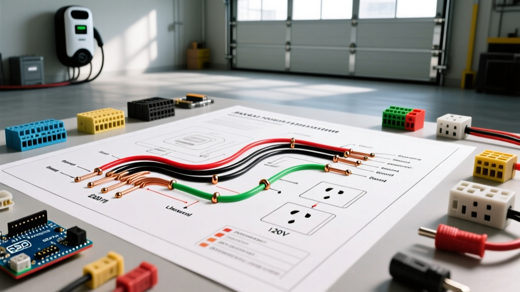
Below are the exact wiring paths for the two most common configurations. Always verify your access control board's relay ratings; most modern boards handle up to 2A at 30VDC, which is sufficient for a single strike.
1. Wiring a Fail-Secure Strike (Normally Open Relay)
This configuration applies power to unlock the door. When the access control system grants access, it closes the NO relay, completing the circuit.
- Step 1: Run the Positive (+) output from your 12VDC/24VDC power supply to the COM (Common) terminal on the access control board's relay.
- Step 2: Run a wire from the NO (Normally Open) terminal on the relay to the Positive (+) terminal on the electric strike.
- Step 3: Run a wire from the Negative (-) terminal on the electric strike directly back to the Negative (-) terminal on the power supply.
- Step 4: Install a 1N4002 rectifier diode directly across the strike's terminals. The silver stripe (cathode) must point toward the Positive (+) wire. This provides a path for back-EMF to dissipate safely.
2. Wiring a Fail-Safe Strike (Normally Closed Relay)
This configuration removes power to unlock the door. The circuit is normally closed, keeping the strike energized and locked. When access is granted (or a fire alarm triggers), the relay opens, cutting power.
- Step 1: Run the Positive (+) output from the power supply to the COM (Common) terminal on the relay.
- Step 2: Run a wire from the NC (Normally Closed) terminal on the relay to the Positive (+) terminal on the electric strike.
- Step 3: Run a wire from the Negative (-) terminal on the strike back to the power supply's Negative (-).
- Step 4: Install the 1N4002 diode across the strike terminals, stripe to Positive (+).
Integrating Request to Exit (REX) and Door Position Switches
In a professional installation, the access control board needs to know when the door is opened and closed to prevent 'forced door' alarms. This requires a Door Position Switch (DPS), usually a magnetic reed switch.
Wire the DPS to the dedicated 'Door Sense' or 'REX' input on your access control board. If you are using a standalone keypad without a dedicated REX input, you must wire a REX motion sensor in parallel with the strike's trigger circuit (for fail-secure) or use a DPDT relay to isolate the egress circuit from the main access relay.
Critical Protection: Why You Cannot Skip the Diode
An electric strike is an inductive load (a coil of wire). When the relay opens and cuts power, the collapsing magnetic field generates a massive reverse voltage spike (Back Electromotive Force, or Back-EMF). This spike can exceed 100V for a fraction of a millisecond.
If you do not install a flyback diode (for DC circuits) or a Metal Oxide Varistor (for AC circuits), this spike will arc across the physical contacts inside your access control board's relay. Over a few weeks, this arcing will pit the contacts, eventually welding them shut or burning out the board's trace. A $0.05 1N4002 diode saves a $600 access control board.
Real-World Troubleshooting & Edge Cases
Even with a perfect wiring diagram, physical installations present unique challenges. Here are the most common failure modes encountered in the field:
The Strike Buzzes but Fails to Release
Cause 1: Voltage Drop. Measure the voltage at the strike's terminals while the strike is actively buzzing. If it reads below 10.5V (on a 12V system), your wire gauge is insufficient, or the power supply is current-limiting.
Cause 2: Door Preload (Mechanical Bind). If the weatherstripping is too thick or the door hinges are sagging, the latch bolt is being pulled tightly against the strike keeper. Standard solenoids cannot overcome this friction.
Fix: Install an electric strike with an adjustable lip or a 'no-load' release mechanism, such as the HES 9600, which is engineered to release the keeper even with up to 25 lbs of preload.
The Strike Gets Hot and Burns Out
Cause: Supplying AC voltage to a DC solenoid, or leaving a continuous-duty rated strike energized 24/7 without adequate heat dissipation.
Fix: Verify the power supply output with a multimeter. If your strike is rated for 12VDC, ensure the transformer is outputting pure DC, not the 12VAC commonly used for older CCTV cameras or HVAC thermostats. If using a 24VAC strike, ensure the internal thermal fuse has not tripped due to a jammed keeper.
Access Control Board Resets When Strike Fires
Cause: Inrush current from the strike is pulling the power supply voltage down so low that the access control board's microcontroller browns out and reboots.
Fix: Separate the power supplies. Use one dedicated Altronix power supply for the locking hardware, and a separate, smaller power supply for the logic board. Tie their DC negatives together to establish a common ground reference.