
Mastering the Honda Shadow Electrical Architecture for Accessory Installs
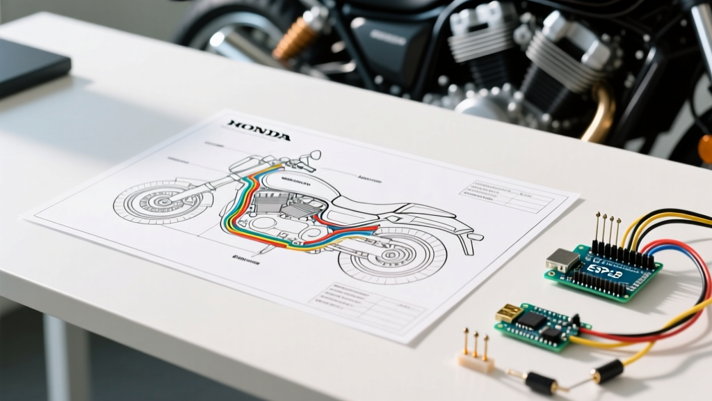
The Honda Shadow lineage—spanning the venerable VT600, the ubiquitous VT750, and the powerful VT1100—represents some of the most reliable cruiser platforms ever built. However, as of 2026, many of these motorcycles are two to three decades old, and their original wiring harnesses are showing their age. Whether you are installing auxiliary LED driving lights, heated grips, or a modern digital dash, relying on a forum sketch is a recipe for a melted connector or a dead stator. To execute a flawless installation, you must use the official electrical wiring Honda Shadow wiring diagram as your master blueprint.
This installation planning guide will walk you through decoding the factory schematics, calculating your charging system's surplus capacity, and routing new circuits using automotive-grade standards.
Decoding the Charging System: What the Diagram Won't Tell You
Before tapping into any circuit, you must understand the physical limits of the Shadow's charging system. The factory service manual (FSM) wiring diagram shows you where the wires go, but it doesn't explicitly warn you about the marginal surplus wattage available on older models.
Expert Insight: The stock Honda Shadow stator produces approximately 380 to 420 watts at 5,000 RPM. However, the bike's baseline electrical load (ignition, headlight, taillight, and instrument cluster) consumes roughly 250 to 300 watts. This leaves you with a usable surplus of only 80 to 120 watts for accessories. Exceeding this will drain the battery at idle and eventually cook the stock shunt-style Regulator/Rectifier (R/R).
If your installation plan includes high-draw items like 60W halogen fog lights or a heated jacket liner (up to 90W), you must upgrade to a series-type MOSFET regulator/rectifier before proceeding. According to diagnostic guidelines from Electrosport Industries, testing your stator's AC output across the three yellow wires (which should read over 50VAC at 3,000 RPM) is a mandatory prerequisite before adding any new electrical load to the system.
Accessory Load Planning & Wire Gauge Selection
Proper wire gauge selection prevents voltage drop and reduces the risk of electrical fires. The electrical wiring Honda Shadow wiring diagram uses specific color codes, but when adding aftermarket circuits, you should adhere to standard AWG (American Wire Gauge) sizing based on your fused load.
| Accessory Type | Typical Amp Draw | Min. Wire Gauge (Run < 10ft) | Recommended Fuse | Relay Required? |
|---|---|---|---|---|
| USB Charger (QuickCharge 3.0) | 2.5A - 3.0A | 18 AWG | 5A Inline | No |
| Heated Grips (Dual Zone) | 4.0A - 6.0A | 16 AWG | 10A Inline | Optional |
| LED Aux Driving Lights | 8.0A - 12.0A | 14 AWG | 15A Inline | Yes (30A Bosch) |
| Heated Jacket Liner | 7.0A - 10.0A | 14 AWG | 15A Inline | Yes (30A Bosch) |
Step-by-Step Installation Planning Using the Diagram
When you open the FSM or a trusted Haynes Motorcycle Manual, the wiring schematic can look like a bowl of spaghetti. Here is how to systematically plan your installation using the diagram.
Step 1: Identify Switched vs. Unswitched Power
You never want to wire an accessory directly to the battery without a relay and a switched trigger, unless it's a memory circuit (like a GPS tracker). Look at the diagram to locate the tail light wire or the ignition switch output. On most Honda Shadows, the tail light wire is switched (hot only when the key is ON). Tapping this wire with a Posi-Tap or a proper solder-and-heat-shrink splice provides a low-amp trigger signal for your relay.
Step 2: Map the Grounding Strategy
Honda's electrical architecture relies heavily on the frame for grounding, but older Shadows suffer from rust and corrosion at frame ground points. The diagram will show ground symbols attached to the frame. Do not rely on the frame for high-draw aftermarket accessories. Instead, run a dedicated 12 AWG or 14 AWG ground wire directly from your accessory harness back to the negative battery terminal or the main engine ground strap bolt.
Step 3: Integrate a Bosch-Style Relay
For any accessory drawing over 5 amps, a standard ISO mini relay (Bosch-style 30A) is mandatory. Here is how to map the relay pins to your Shadow's wiring:
- Pin 30 (Power In): Connect directly to the battery positive via a 15A inline fuse. The fuse must be located within 6 inches of the battery terminal.
- Pin 87 (Power Out): Routes to your accessory (e.g., LED light bar).
- Pin 86 (Switched Trigger): Connect to the switched 12V source you identified in the Honda Shadow wiring diagram (e.g., tail light wire).
- Pin 85 (Ground): Connect to your dedicated battery-negative ground wire.
Common Wiring Pitfalls & Failure Modes
Even with the electrical wiring Honda Shadow wiring diagram in hand, DIYers frequently fall into the same traps. Avoid these specific failure modes:
- The Infamous 3-Pin Yellow Connector: The connector linking the stator to the R/R is notorious for melting due to resistance and heat. If you are doing any major wiring overhaul, cut this connector out and solder the three yellow wires directly together, sealing them with adhesive-lined heat shrink.
- Using Scotch-Loks (Vampire Taps): Never use T-taps on a motorcycle. The vibration of a V-twin engine will cause these taps to loosen, slice through the copper strands, and introduce moisture into the harness. Always use Posi-Taps, solder sleeves, or crimp-and-seal butt connectors.
- Ignoring the Pulse Generator Coil: When routing wires near the left side of the engine, be hyper-aware of the pulse generator (pickup coil) wiring. Chafing these wires against the crankcase will cause the CDI/ignition module to misfire or fail entirely, leaving you stranded.
Connector Standards for the Modern DIYer
In 2026, there is no excuse for using cheap vinyl electrical tape and twisted wires. To ensure your installation matches OEM reliability, invest in the following connection methods:
- Adhesive-Lined Heat Shrink: Use dual-wall heat shrink with an inner meltable adhesive layer. When heated, it creates a waterproof seal that prevents capillary action from wicking moisture down the wire strands.
- Sumitomo HM 090 Connectors: If you are building a custom harness for auxiliary lights, use Sumitomo or JST SM connectors with proper crimping dies. These offer the same vibration resistance as the factory Honda connectors.
- Deutsch DT Plugs: For removable accessories like tank bags with integrated USB or heated gear, 2-pin Deutsch DT plugs provide a rugged, waterproof quick-disconnect solution.
Sourcing Authentic Diagrams and Manuals
While you can find low-resolution scans of the Honda Shadow wiring diagram on various forums, these are often illegible, missing the ground distribution charts, or specific to the wrong model year. A VT750C Aero diagram is vastly different from a VT750DC Spirit diagram due to differences in the instrument cluster and turn signal modules.
Always source your diagrams from a Factory Service Manual (FSM) specific to your exact model year and VIN prefix. Clymer and Haynes manuals are excellent secondary resources that often include simplified, color-coded wiring schematics that are easier to read on a workbench than the microscopic fold-outs found in the OEM Honda manuals.
Final Pre-Flight Checks
Before reassembling the side covers and taking your Shadow for a test ride, perform a systematic continuity and voltage drop test. With the bike running at 3,000 RPM, use a multimeter to verify that your battery is reading between 13.8V and 14.4V with all new accessories switched on. If the voltage drops below 13.2V, your accessory load has exceeded the stator's capacity, and you must either reduce the load or upgrade to a high-output stator.
By respecting the limits of the charging system and strictly following the electrical wiring Honda Shadow wiring diagram, you will build a robust, reliable electrical system capable of handling modern accessories without compromising the legendary reliability of your cruiser.