
Understanding the Hayward Pool Pump Wiring Diagram
Wiring a swimming pool circulation pump requires strict adherence to electrical safety codes and precise terminal configurations. Whether you are installing a classic single-speed Hayward Super Pump (SP2600 series) or a modern variable-speed TriStar VS model, interpreting the wiring diagram for Hayward pool pump motors is the most critical step in preventing motor burnout, nuisance tripping, and severe shock hazards. As of 2026, the U.S. Department of Energy mandates variable-speed pumps for most new residential pool constructions, yet millions of single and dual-speed induction motors remain in active service, requiring meticulous maintenance and rewiring.
This comprehensive appliance wiring tutorial breaks down the exact terminal board configurations, National Electrical Code (NEC) Article 680 requirements, and wire gauge selections necessary for a safe, long-lasting installation. A standard 1.5 HP Hayward Super Pump currently retails between $650 and $850, while advanced variable-speed models like the TriStar VS SP3220EEVS can exceed $1,400. Protecting this investment starts at the circuit breaker and ends at the motor terminal block.
Critical Safety Warning: All pool pump wiring must comply with NEC Article 680. According to the National Fire Protection Association (NFPA), pool pumps must be protected by a Class A Ground-Fault Circuit Interrupter (GFCI) and connected to an equipotential bonding grid. Never bypass GFCI protection or omit the bonding wire.
Decoding the Motor Terminal Board and Voltage Selector
Hayward pool pumps typically utilize Century (formerly A.O. Smith) or Marathon electric motors. These motors are dual-voltage, meaning they can operate on either 115V or 230V. However, the motor does not automatically detect the voltage; it must be manually configured. Modern motors feature a small voltage selector switch on the back of the terminal housing, while older models require physically moving a jumper wire on the terminal board.
Voltage and Breaker Sizing Matrix
Selecting the correct breaker and THWN-2 copper wire gauge is dictated by the motor's Full Load Amps (FLA) and Service Factor (SF). Below is the standard sizing chart for common Hayward pump motors operating at 60Hz.
| Motor HP | Voltage | Max FLA (Amps) | Breaker Size | Copper Wire Gauge (THWN-2) |
|---|---|---|---|---|
| 1.0 HP | 230V | 7.4A | 15A | 14 AWG (12 AWG Recommended) |
| 1.5 HP | 230V | 9.3A | 20A | 12 AWG |
| 2.0 HP | 230V | 12.0A | 20A | 12 AWG |
| 1.5 HP | 115V | 18.6A | 30A | 10 AWG |
| 2.0 HP | 115V | 24.0A | 35A | 8 AWG |
Note: For conduit runs exceeding 100 feet, you must increase the wire gauge by one size to compensate for voltage drop, which can cause the motor to overheat and fail prematurely.
Step-by-Step 230V Wiring Tutorial (Dedicated Circuit)
The vast majority of in-ground Hayward pool pumps are wired for 230V. This configuration is highly efficient, reduces current draw by half compared to 115V, and minimizes voltage drop over long distances from the main service panel to the pool equipment pad.
Step 1: Pulling the Conduit and Conductors
- Run a minimum of 3/4-inch Schedule 80 PVC conduit from the pool equipment subpanel to the pump motor.
- Pull three THWN-2 stranded copper wires: Line 1 (Black), Line 2 (Red), and Ground (Green or Bare).
- Do not pull a neutral wire for a standard 230V single-phase pump motor. The neutral is only required if you are wiring a 115V control circuit or a specific automation relay that requires 120V.
Step 2: Terminating the Motor Leads
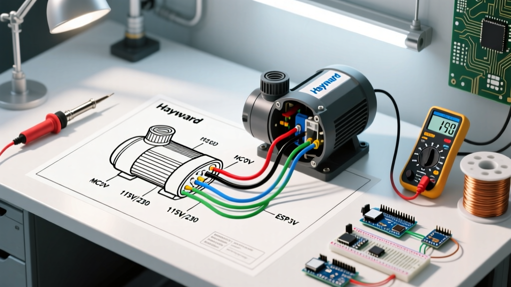
Open the rear electrical cover of the Hayward motor. Ensure the voltage selector switch is firmly clicked into the 230V position. If your motor uses a terminal board with screws labeled 1, 2, 3, 4, 5, P, and A:
- Line 1 (Black): Connect to Terminal L1.
- Line 2 (Red): Connect to Terminal L2.
- Ground (Green): Connect to the internal grounding screw (usually painted green or marked 'GR').
Pro-Tip: Use a calibrated torque screwdriver to tighten the terminal screws to 12-15 in-lbs. Loose connections cause arcing, which generates intense heat and will melt the terminal block, leading to a catastrophic motor failure.
Step 3: Establishing the Equipotential Bonding Grid
Bonding is entirely separate from grounding. While the ground wire clears a fault, the bonding grid ensures all metallic components within 5 feet of the pool are at the exact same electrical potential, preventing lethal shock. According to NEC 680.26, you must use a solid #8 AWG copper bonding wire. Connect this wire to the external copper bonding lug located on the outside of the Hayward motor housing, and daisy-chain it to the pool shell rebar, the metal pool wall, and the equipment pad grounding bar.
Integrating GFCI Protection and Automation
Under current NEC guidelines, a pool pump cannot simply be connected to a standard double-pole breaker. It requires GFCI protection. You have two primary options:
- GFCI Circuit Breaker: Install a 20A, 230V GFCI breaker (such as a Square D Homeline or Siemens QAF2) directly in the subpanel. These breakers typically cost between $60 and $95 in 2026 and feature a coiled neutral pigtail that must connect to the panel's neutral bar, even if the pump itself does not use a neutral.
- GFCI Disconnect Switch: Use a standard breaker at the main panel and install an outdoor-rated GFCI spa panel/disconnect switch within sight of the pump (at least 5 feet away from the pool edge).
If you are integrating the pump with a Hayward OmniLogic or AquaPlus automation system, the pump's line voltage will be routed through the system's high-voltage relays, while a low-voltage RS485 data cable will control variable-speed models.
Variable Speed (TriStar VS) Data Wiring
For those upgrading to a Hayward TriStar VS or Super Pump VS, the high-voltage wiring remains identical to the 230V guide above. However, these pumps require a low-voltage communication cable to interface with automation boards or standalone digital controllers.
- Use a 2-conductor, 18 AWG shielded twisted-pair cable.
- Connect the wires to the RS485 terminal block on the pump's rear drive housing.
- Polarity matters on some older Hayward boards, but modern RS485 networks are generally polarity-insensitive. Ensure the shield drain wire is grounded at the automation controller end only, to prevent ground loops that cause communication dropouts.
For more on the energy savings associated with these advanced motors, refer to the U.S. Department of Energy's guidelines on swimming pool pump efficiency.
Troubleshooting Common Wiring and Motor Faults
Even with a perfect wiring diagram for your Hayward pool pump, environmental factors and component aging can cause operational issues. Here is how to diagnose the most frequent failures:
Motor Hums but Fails to Start
This is rarely a wiring fault and almost always a component failure. The motor's centrifugal switch may be stuck, or the start capacitor has failed. Using a multimeter with a capacitance setting, test the start capacitor (typically a black cylindrical component under the rear hump). A 1.5 HP motor usually requires a 370V, 25µF to 50µF capacitor. If the reading is more than 10% below the rated microfarads, replace it.
GFCI Nuisance Tripping
If your GFCI breaker trips immediately upon startup, you likely have a ground fault. Water intrusion into the terminal housing is a common culprit. Check the rear conduit hub; if the silicone sealant has degraded, rain or sprinkler water can travel down the conduit into the motor. Additionally, a failing shaft seal can allow pool water to weep past the impeller and into the motor windings, creating a direct path to ground. If the motor is wet internally, it must be rebuilt or replaced. For genuine replacement parts and schematics, consult Hayward Pool Products directly.
Overheating and Thermal Overload Tripping
If the pump runs for 15 minutes and then shuts off, only to restart an hour later, the internal thermal overload protector is doing its job. This is caused by inadequate ventilation (pump installed under a tight deck), blocked impeller vanes causing the motor to work harder, or severe voltage drop. Measure the voltage at the motor terminals while the pump is running; if it drops below 218V on a 230V circuit, you must upgrade your wire gauge or shorten the conduit run.
Final Inspection and Commissioning
Before energizing the circuit for the first time, perform a final visual inspection. Ensure no stray strands of copper wire are bridging the gap between L1 and L2. Verify that the #8 AWG bonding wire is tightly clamped to the external lug with a brass or bronze nut (never use steel, which will rust and compromise the safety grid). Prime the pump basket with water, close the air relief valve, and engage the breaker. A properly wired Hayward pool pump should start smoothly within one second, running quietly and efficiently for years to come.