
Beyond the Terminals: Why Amplifier Circuits Require Panel Integration
When most DIY enthusiasts and junior AV installers search for a wiring diagram for speakers, they focus exclusively on the low-voltage side: routing 14 AWG wire from binding posts to in-wall volume controls and ceiling drivers. However, in modern whole-house audio and commercial distributed sound systems, the most critical point of failure actually begins at the main electrical panel. High-output multi-zone amplifiers demand stable, clean AC power. Sharing a standard 15A lighting circuit with LED dimmers or smart switches introduces electromagnetic interference (EMI) and voltage sags that degrade audio fidelity and can prematurely destroy sensitive Class-D amplifier switching power supplies.
This guide bridges the gap between low-voltage audio routing and high-voltage panel integration, providing a comprehensive, code-compliant approach to sizing breakers, routing AC power, and terminating your speaker wiring diagram for optimal 2026 AV rack performance.
NEC Code Compliance: Line Voltage vs. Low Voltage Separation
Before pulling a single wire, you must understand the National Electrical Code (NEC) boundaries governing audio installations. According to the National Fire Protection Association (NFPA) NEC Guidelines, audio systems fall under specific articles that dictate how line voltage (120V AC) and low voltage (speaker wire) must interact.
- NEC Article 640: Covers Audio Signal Processing, Amplification, and Reproduction Equipment. It mandates that speaker wires must not be placed in the same enclosure, conduit, or junction box as line-voltage power wiring unless separated by a permanent physical barrier.
- NEC Article 725: Classifies speaker wire as Class 2 or Class 3 power-limited circuits. You must use CL2 or CL3 rated jacketed wire for any in-wall or ceiling speaker runs to prevent fire propagation.
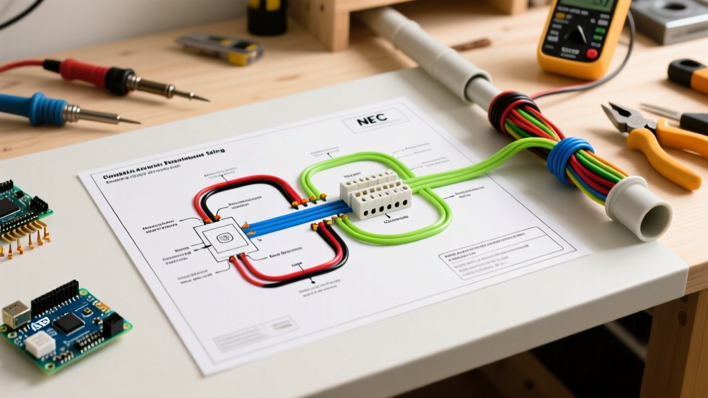
Expert Rule of Thumb: Maintain a minimum physical separation of 2 inches between parallel runs of 120V AC Romex and CL2 speaker wire. If the wires must cross, ensure they intersect at a strict 90-degree angle to minimize inductive hum.
The Complete Wiring Diagram for Speakers & Power
A professional whole-house audio wiring diagram is split into two distinct phases: the dedicated AC power circuit and the low-voltage speaker distribution network.
Phase 1: Sizing and Routing the Dedicated 20A Breaker Circuit
Modern multi-zone amplifiers (such as the Sonos Amp at $699 or commercial Crown CDi DriveCore models exceeding $1,400) utilize Switching Mode Power Supplies (SMPS). While highly efficient, SMPS units draw massive inrush current upon startup and generate high-frequency harmonic noise.
- Breaker Selection: Install a dedicated 20A single-pole thermal-magnetic breaker in your main panel. Avoid placing AV equipment on AFCI (Arc-Fault Circuit Interrupter) breakers if local code permits an exception, as the inrush current and SMPS noise can cause nuisance tripping. If 2026 local codes strictly mandate AFCI for the room where the rack resides, use a newer-generation AFCI breaker with advanced algorithmic filtering to distinguish between arc faults and SMPS startup signatures.
- Wire Gauge: Run 12/2 NM-B (Romex) copper wire from the 20A breaker to a dedicated, hospital-grade duplex receptacle mounted directly behind the AV rack.
- Power Conditioning: Terminate the receptacle into a high-capacity power conditioner, such as the Furman P-1800 PF (approx. $1,100), which provides inrush current limiting, EMI filtering, and over-voltage shutdown protection.
Phase 2: Low-Voltage Speaker Routing
With clean, conditioned power established, the low-voltage wiring diagram for speakers follows a star topology originating from the amplifier rack.
- Main Trunks: Use 12 AWG or 14 AWG CL2-rated, oxygen-free copper (OFC) speaker wire for runs exceeding 50 feet to prevent impedance-related frequency loss.
- Impedance Matching: If wiring multiple speakers in parallel to a single amplifier zone, integrate an impedance-matching volume control (e.g., Russound or Speakercraft) at the wall to ensure the total load never drops below the amplifier's stable minimum (usually 4 ohms).
- Termination: Use banana plugs at the amplifier end for secure, high-surface-area contact, and bare wire or spade lugs at the in-wall speaker terminals to prevent corrosion behind the drywall.
Amplifier Power Draw & Breaker Sizing Matrix
Use the table below to determine the correct panel integration strategy based on your specific amplifier hardware. Continuous current is calculated assuming a 120V AC supply and accounting for typical Class-D efficiency (approx. 90%).
| Amplifier Type / Example Model | Max Power Draw (Watts) | Continuous Current (Amps) | Recommended Breaker | AC Wire Gauge |
|---|---|---|---|---|
| Single-Zone Streaming Amp (e.g., Sonos Amp) | 220W | ~2.0A | 15A or 20A Dedicated | 14/2 or 12/2 NM-B |
| 4-Zone Matrix Amp (e.g., Control4 EA-4) | 600W | ~5.5A | 20A Dedicated | 12/2 NM-B |
| Commercial 70V Amp (e.g., Crown CDi 4|1200) | 1400W | ~13.0A | 20A Dedicated | 12/2 NM-B |
| High-Current Audiophile Mono-Blocks (x2) | 2500W+ | ~23.0A+ | 30A Dedicated (or 240V) | 10/2 NM-B |
Common Failure Modes in AV Panel Integration
Even with a perfect wiring diagram for speakers, improper electrical panel execution leads to frustrating post-installation failures. Here is how to troubleshoot the most common edge cases:
1. The 'Dimmer Switch Hum' (Ground Loops & EMI)
Symptom: A persistent 60Hz or 120Hz hum from the speakers that changes pitch when adjusting smart lighting dimmers in the home.
Cause: The amplifier shares a circuit with TRIAC-based LED dimmers, which chop the AC sine wave and inject harmonic noise back into the neutral bus.
Fix: Move the amplifier to its own dedicated 20A circuit. If the hum persists, the issue is a ground loop between the AV rack and a connected display. Install a ground loop isolator or ensure all AV components share a single common ground point at the power conditioner.
2. Nuisance AFCI Tripping on Startup
Symptom: The breaker trips instantly when the AV rack is powered on via a smart relay or trigger, but holds fine if turned on manually one component at a time.
Cause: Simultaneous startup of multiple SMPS amplifiers creates a massive inrush current spike (sometimes 40A+ for milliseconds) that the AFCI breaker misinterprets as a parallel arc fault.
Fix: Implement sequential power triggering. Use a power conditioner with built-in delay sequencing (e.g., delaying Zone 2 amp startup by 3 seconds after Zone 1) to stagger the inrush current draw.
3. High-Frequency Roll-Off in Ceiling Speakers
Symptom: Vocals sound muffled; treble is missing in distant rooms.
Cause: Using undersized 16 AWG or 18 AWG wire for runs exceeding 70 feet. The resistance of the thin wire acts as a low-pass filter in conjunction with the speaker's crossover network.
Fix: Consult the U.S. Department of Energy guidelines on home electrical systems regarding voltage drop. Upgrade long runs to 12 AWG CL2 speaker wire to keep total circuit resistance below 5% of the speaker's nominal impedance.
Expert FAQs
Can I wire 70V commercial speakers on the same diagram as 8-ohm residential speakers?
No. 70V distributed audio systems require a step-up transformer at the amplifier and step-down transformers at each speaker tap. Connecting a standard 8-ohm residential speaker directly to a 70V line will instantly destroy the speaker voice coil and potentially trigger the amplifier's short-circuit protection. Keep 70V and low-impedance wiring diagrams completely isolated.
Do I need to bond the AV rack to the home's main grounding electrode?
Yes. The AV rack should be bonded to the home's grounding system using a minimum 6 AWG copper grounding wire connected to the main panel's ground bus or an approved grounding electrode conductor. This ensures that in the event of a catastrophic power supply failure, the fault current has a low-impedance path to trip the breaker, protecting both the equipment and the user.
Is it safe to run speaker wire inside HVAC return air ducts?
Only if the speaker wire is specifically rated as CL2P or CL3P (Plenum-rated). Standard CL2 wire will emit toxic fumes if it catches fire inside an air handling space, violating NEC Article 300.22. Always verify the jacket stamping on the wire spool before routing through drop ceilings or cold air returns.