
The Evolution of BOSS V-Plow Electrical Architecture
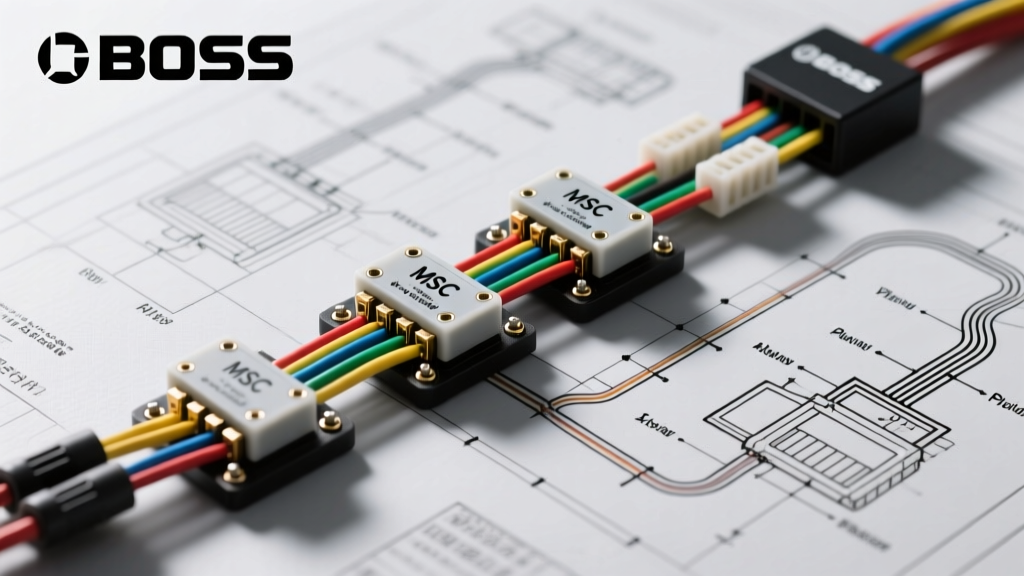
Installing a snowplow is a significant mechanical and electrical undertaking. When reviewing the wiring diagram for BOSS V plow setups, it is critical to understand that the electrical architecture has evolved dramatically over the last decade. Older XT models relied on heavy-duty, 4-relay solenoid systems that required thick, direct-run power cables for every hydraulic valve function. Today, modern BOSS V-plows—specifically the V-XT and DXT series—utilize the Multiplex Smart Control (MSC) architecture. This system drastically reduces the number of wires crossing the grille by sending digital data signals alongside a primary power feed, shifting the heavy switching logic to a smart module mounted directly on the plow.
As of 2026, planning your installation requires a firm grasp of both the high-amperage hydraulic pump circuits and the low-voltage multiplex data lines. A misrouted data line or an undersized ground cable will result in erratic blade movement, dropped communication codes, or catastrophic module failure. This guide breaks down the exact specifications, routing strategies, and failure modes you need to execute a flawless installation.
Core Components in the Wiring Diagram for BOSS V Plow Models
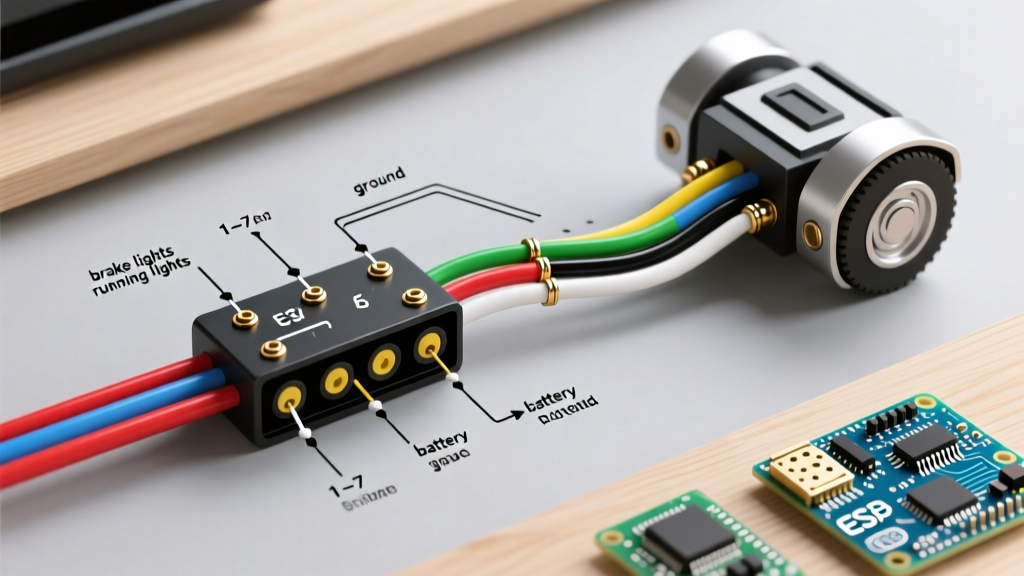
Before cutting zip ties or stripping wire, you must inventory the specific electrical components required for your build. The modern BOSS V-plow wiring diagram is divided into two primary domains: the vehicle-side harness and the plow-side harness.
- MSC Module (Multiplex Smart Control): The brain of the plow. It receives digital commands from the in-cab controller and actuates the hydraulic valves. Replacement units currently retail between $380 and $450.
- Vehicle-Side Harness Kit: Includes the main power cables, the cab-to-grille data/power whip, and the in-cab control pad wiring. Expect to invest $280 to $350 for a complete OEM kit.
- Plow-Side Harness: Routes power from the grille connector to the MSC module, hydraulic pump motor, and lighting circuits.
- Hydraulic Pump Motor & Solenoid: The primary current draw on the system, requiring dedicated, high-gauge power and ground paths.
- In-Cab Controller: The touchpad or joystick that communicates via the vehicle's CAN bus or a dedicated serial line to the grille connector.
Wire Gauge and Amperage Planning Matrix
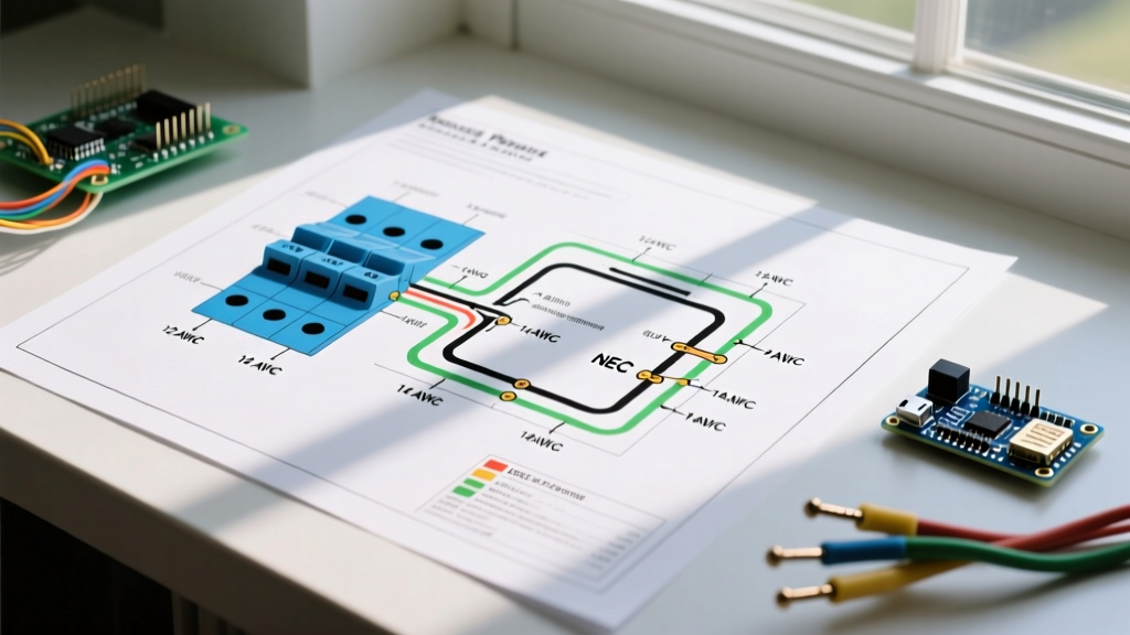
Adhering to proper wire gauge specifications is non-negotiable. Voltage drop across long cable runs in cold weather (where copper resistance changes and battery output drops) is the leading cause of hydraulic pump stalling. The following matrix outlines the minimum requirements based on SAE automotive electrical standards for auxiliary high-draw equipment.
| Circuit Function | Minimum Wire Gauge (AWG) | Peak Amperage Draw | Insulation / Routing Requirement |
|---|---|---|---|
| Main Power (Battery to Solenoid/Pump) | 2 AWG | 150A - 180A | Heavy-duty jacket, split loom, away from exhaust |
| Main Ground (Pump to Engine Block) | 2 AWG | 150A - 180A | Must terminate to bare metal on engine block, not chassis |
| MSC Power Feed (Grille to Module) | 10 AWG | 30A | Standard automotive primary wire, fused at source |
| Data / Control Lines (Cab to Grille) | 18 AWG (Shielded) | < 2A | Must be routed separately from high-current power lines |
| Lighting Harness (Headlights/Markers) | 14 AWG | 10A - 15A | Standard loom, waterproof connectors at grille |
Reference: For comprehensive automotive wiring standards and voltage drop calculations, consult the SAE International Standards database, specifically SAE J1128 for low-tension primary cable specifications.
Step-by-Step Routing and Connection Strategy
Proper physical routing is just as important as the electrical schematic. Follow this sequence to ensure longevity and prevent chafing or electromagnetic interference (EMI).
- Establish the Dedicated Ground: Do not ground the 2 AWG plow ground wire to the truck's sheet metal or frame. You must route it directly to the engine block or the primary negative battery terminal. Clean the mating surface with a wire wheel to bare metal, apply a conductive anti-corrosion compound, and torque to manufacturer specifications.
- Run the Main Power Feed: Route the 2 AWG red power cable from the battery positive terminal to the heavy-duty solenoid (usually mounted in the engine bay). Install a 150A mega-fuse within 8 inches of the battery terminal to protect against dead shorts.
- Separate Data and Power Lines: When running the vehicle-side cab-to-grille harness through the firewall, keep the 18 AWG data lines at least 4 inches away from the 2 AWG power lines and ignition coils. This prevents EMI from corrupting the multiplex signals, which causes the controller to throw 'Loss of Communication' errors.
- Create Drip Loops: At every exterior connection point—especially the main 11-pin or 13-pin grille connector—form a physical drip loop in the wiring harness. This ensures that melting snow and road spray drip off the bottom of the loop rather than wicking directly into the connector housing.
- Secure with Adhesive-Lined Heat Shrink: For any splices or terminal crimps, use adhesive-lined marine-grade heat shrink. Standard electrical tape will unspool within one season due to the extreme temperature fluctuations and chemical exposure (road salt and magnesium chloride) inherent to winter operations.
Managing EMI and Data Line Integrity
The shift to the MSC system means your plow relies on digital handshakes rather than simple 12V triggers. If the data lines are compromised by Electromagnetic Interference (EMI) from the truck's alternator or ignition system, the plow will behave erratically. Always use shielded cable for the data lines, and ensure the shield drain wire is grounded at the cab side only to prevent ground loops.
Pro-Tip for Connector Maintenance: Never use standard silicone spray on the main grille connector. Use a dedicated, non-conductive dielectric grease (like Nyogel 760G or equivalent) packed heavily into the female pins of the 13-pin connector. This displaces moisture and prevents the galvanic corrosion that plagues plow wiring in salt-heavy environments.
Common Failure Modes and Edge Cases
Even with a perfect installation, environmental factors can induce specific failure modes. Understanding these edge cases will save you hours of troubleshooting in freezing temperatures.
1. The 'Ghost' Valve Actuation
Symptom: The plow blade drops or angles slightly without user input, often accompanied by a flickering LED on the in-cab controller.
Root Cause: Moisture intrusion in the cab-to-grille data connector causing cross-talk between multiplex pins, or a failing MSC module experiencing internal logic faults due to thermal shock.
Solution: Inspect the grille connector for bent pins or green copper oxide. If the connector is clean, perform a CAN bus/data line continuity test. If the data lines are intact, the MSC module (Part # MSC05031 or current generation equivalent) likely requires replacement.
2. Hydraulic Pump Bogs Down Under Load
Symptom: The plow lifts slowly or stalls when angling against a heavy snowbank, and the truck's headlights dim noticeably.
Root Cause: Severe voltage drop on the ground circuit. While the power wire may be 2 AWG, installers often use a corroded chassis ground or an undersized 4 AWG wire for the return path.
Solution: Use a digital multimeter (such as a Fluke 87V) to measure the voltage drop across the ground cable while the pump is under maximum load. A reading higher than 0.2V indicates excessive resistance. Upgrade the ground wire and clean the engine block termination point.
3. MSC Module Thermal Shutdown
Symptom: The plow operates perfectly for the first 10 minutes, then completely shuts down and will not reset until it cools.
Root Cause: The MSC module was mounted too close to the truck's exhaust manifold, radiator fan, or in an area with zero airflow, causing the internal thermal protection to trip.
Solution: Relocate the MSC module to a higher position on the plow headgear or behind the moldboard where it is shielded from direct engine heat but still exposed to ambient winter air for cooling.
Final Testing and Calibration Protocol
Before bolting the plow to the truck for the first time, execute a bench-and-bay test. Connect the fully assembled wiring harness to the truck's battery and the plow's MSC module, leaving the hydraulic fluid reservoir empty to prevent accidental pressurization.
- Turn on the in-cab controller and verify the 'Plow Connected' indicator illuminates immediately.
- Use the controller to cycle through all directional commands. Listen for the distinct 'click' of the MSC internal relays and the hydraulic valve coils engaging.
- Check the lighting harness: verify that the plow headlights, turn signals, and marker lights operate in sync with the truck's OEM lighting circuit.
- Inspect all routing points one final time to ensure no wiring is resting against sharp steel edges, the steering shaft, or hot exhaust components.
For official schematic downloads, part numbers, and firmware updates for your specific serial number, always refer to the BOSS Snowplows Technical Support portal. Proper planning and strict adherence to the wiring diagram for BOSS V plow systems will ensure your equipment survives the harshest winter conditions while delivering reliable, heavy-duty performance.