
Introduction to White-Rodgers Heat Motor Actuators
When working on residential and light commercial hydronic heating systems, understanding the specific actuation mechanism of your zone valves is critical for proper wiring and troubleshooting. Unlike the synchronous motors found in competing brands, White-Rodgers zone valves utilize a unique thermal heat motor. This motor relies on the thermal expansion of a specialized compound to push a bellows, slowly and quietly opening the valve without the abrupt mechanical snapping associated with gear-driven actuators.
Because of this distinct operating principle, the wiring diagram for White Rodgers zone valve setups differs slightly in transformer sizing and end-switch behavior compared to standard motorized valves. In this comprehensive motor wiring tutorial, we will break down the exact wiring configurations for the industry-standard White-Rodgers 1361 series, calculate precise VA (Volt-Ampere) loads, and provide actionable troubleshooting steps for common field failures.
White-Rodgers 1361 Series Specifications
Before pulling wire, you must verify the exact model number on the actuator head. The 1361 series is the most prevalent in modern hydronic systems. Below are the critical electrical specifications you need for your wiring plan.
| Model Number | Configuration | Voltage | Inrush / Holding VA | End Switch |
|---|---|---|---|---|
| 1361-102 | 2-Wire Actuator | 24V AC, 50/60Hz | ~15 VA / ~15 VA | No |
| 1361-103 | 3-Wire Actuator | 24V AC, 50/60Hz | ~15 VA / ~15 VA | Yes (SPDT) |
| 1361-104 | 2-Wire (Normally Open) | 24V AC, 50/60Hz | ~15 VA / ~15 VA | No |
Note: Because heat motors do not experience the massive mechanical inrush spikes of synchronous motors, the holding VA and inrush VA are nearly identical, making transformer sizing much more predictable.
Decoding the Wiring Diagram for White Rodgers Zone Valve Actuators
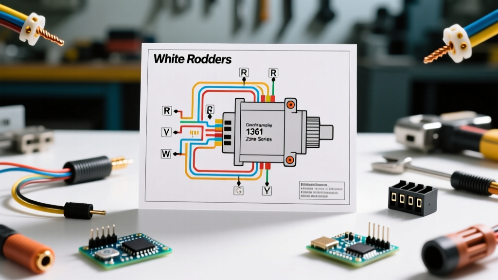
The physical wiring diagram for White Rodgers zone valve systems is generally printed on a label located under the actuator cover or on the installation sheet tucked inside the box. Here is how to interpret the core circuits.
The 2-Wire Setup (Model 1361-102)
The 1361-102 is a straightforward, two-terminal heat motor. It acts as a simple resistive/inductive load.
- Terminal 1: Connects to the 'W' (Heat) terminal of the thermostat or the aquastat.
- Terminal 2: Connects to the common (C) terminal of the 24V AC transformer.
The 3-Wire Setup with End Switch (Model 1361-103)
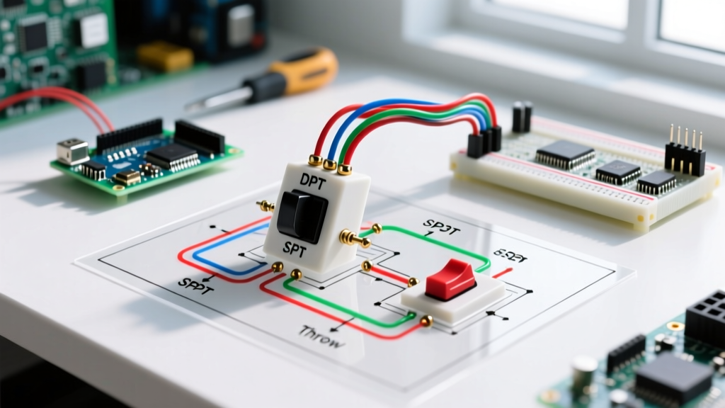
The 1361-103 includes an internal Single-Pole Double-Throw (SPDT) microswitch. This end switch is crucial for systems where the zone valve must prove it has opened before triggering the boiler circulator pump or firing the burner.
- Motor Terminals (2): Wired exactly like the 1361-102 (Thmostat 'W' to Transformer 'C').
- End Switch Common (C): The input for your pump relay or boiler control.
- End Switch Normally Open (NO): Connects to the pump relay coil. This circuit only closes when the valve is fully open.
- End Switch Normally Closed (NC): Rarely used in standard residential setups, but available for bypass or indicator light circuits.
Step-by-Step Motor Wiring Tutorial
Follow this sequence to ensure a safe, code-compliant installation that will last for decades.
Step 1: Power Verification and Wire Selection
Always lock out the 120V/240V primary power to the boiler and air handler. For 24V AC zone valve circuits, the National Electrical Code (NEC) Article 725 classifies this as a Class 2 circuit if powered by a listed Class 2 transformer. Use 18 AWG solid copper thermostat wire. Stranded wire can fray and cause short circuits inside the tight terminal blocks of the valve head.
Step 2: Sizing the Control Transformer
Undersized transformers are the number one cause of premature heat motor failure. If the voltage drops below 20V AC under load, the heat motor will stall, overheat, and eventually burn out its internal winding. According to HVAC School best practices for zone valve wiring, you must calculate the total VA of all valves on a single transformer.
| Transformer Size (VA) | Max White-Rodgers 1361 Valves | Recommended Application |
|---|---|---|
| 40 VA | 2 Valves | Small apartments, single-zone additions |
| 50 VA | 3 Valves | Standard 3-zone residential homes |
| 75 VA | 4 to 5 Valves | Large homes, multi-story hydronic systems |
| 100 VA | 6 Valves (Max Class 2 Limit) | Light commercial, maxed out Class 2 circuits |
Step 3: Routing and Terminating
Route the 18 AWG wire away from high-voltage 120V lines to prevent inductive interference, though less critical for simple thermal motors than for digital communicating valves. Strip exactly 1/4 inch of insulation. Loop the wire clockwise around the screw terminals on the valve head to ensure the screw pulls the wire tight as it is torqued down.
Step 4: End Switch Integration (1361-103 Only)
If using the 1361-103, wire the 'C' and 'NO' terminals of the end switch in series with the boiler's circulator relay or the 'TT' (thermostat) terminals on the aquastat. This ensures the boiler does not fire into a closed valve, which can cause catastrophic heat exchanger thermal shock.
Troubleshooting Common Failure Modes
White-Rodgers heat motors are incredibly reliable, but they do fail under specific conditions. As of 2026, a replacement 1361-102 actuator head typically costs between $60 and $85, while a complete valve body assembly runs $110 to $145. Here is how to diagnose issues before replacing parts:
- Symptom: Valve hums but does not open.
Diagnosis: Low voltage. Check the transformer output under load. If it reads below 22V AC, the transformer is undersized or failing. The heat motor requires a full 24V to generate enough thermal expansion to overcome the water pressure and spring tension. - Symptom: Valve opens, but boiler doesn't fire (1361-103).
Diagnosis: End switch failure. Use a multimeter to check for continuity between the 'C' and 'NO' terminals on the end switch while the valve is fully open. If the motor is hot and the valve stem is depressed, but there is no continuity, the internal microswitch contacts are pitted or burnt. Replace the actuator head. - Symptom: Valve opens extremely slowly (over 5 minutes).
Diagnosis: Ambient temperature interference. Heat motors are sensitive to ambient heat. If the valve is mounted directly above a steam pipe, near a flue, or inside an unventilated enclosure that traps boiler heat, the thermal compound cannot cool down properly, leading to erratic expansion cycles. Relocate the actuator head or add a heat shield.
Code Compliance Note: When wiring multiple zone valves, always adhere to NFPA 70 (NEC) Article 725. If your total connected load exceeds 100 VA, the circuit is no longer considered Class 2. You must then upgrade to 14 AWG wire, utilize proper junction boxes, and protect the circuit with standard overcurrent protection devices, treating it as a Class 1 power-limited circuit.
Frequently Asked Questions
Can I wire a White-Rodgers zone valve to a smart thermostat like Ecobee or Nest?
Yes. Smart thermostats require a 'C' (Common) wire to power their internal Wi-Fi radios and displays. The 'W' terminal on the smart thermostat acts as a solid-state relay, completing the 24V AC circuit to the White-Rodgers heat motor. Ensure your control transformer has at least 10 VA of spare capacity to handle the smart thermostat's continuous power draw alongside the valve's 15 VA load.
Why does my White-Rodgers valve take so long to open compared to my old Honeywell valve?
This is by design. Honeywell valves use a synchronous motor and a gear train to snap open in about 10 to 15 seconds. White-Rodgers uses a thermal expansion bellows that takes 1 to 3 minutes to fully stroke. This slow opening prevents 'water hammer'—the loud banging noise caused by sudden changes in water flow momentum in copper piping.
Is it safe to manually open the valve using the lever while the system is wired?
Yes, the manual opening lever is mechanically linked to the valve stem, bypassing the heat motor entirely. However, if you are using a 1361-103 with an end switch, manually opening the valve will not trigger the end switch. The end switch is only actuated by the downward travel of the heat motor bellows. If you manually open the valve to bleed a radiator, the boiler circulator will not turn on automatically.