
Understanding the 240v Electric Baseboard Heater Wiring Diagram PDF
When planning a supplemental heating installation, locating an accurate 240v electric baseboard heater wiring diagram PDF is the critical first step. While generic internet schematics are plentiful, they frequently omit vital manufacturer-specific grounding lug placements, high-limit switch bypass warnings, and junction box knock-out configurations. Relying on official documentation from industry leaders like Cadet Heat Installation Manuals or King Electric Wiring Diagrams ensures your installation aligns with both the physical constraints of the unit and rigorous safety standards.
A 240-volt baseboard heater operates without a neutral wire, utilizing two hot legs (L1 and L2) and an equipment grounding conductor. Misinterpreting a generic diagram can lead to catastrophic failures, including melted wire insulation, tripped arc-fault breakers, or severe electrical shock hazards. This guide bridges the gap between the manufacturer's PDF schematic and real-world National Electrical Code (NEC) compliance for 2026.
NEC Code Compliance & The 125% Continuous Load Rule
Fixed electric space heating equipment is governed by NEC Article 424. The most common code violation observed in DIY and even some contractor-level installations is failing to size the branch circuit for continuous duty. According to the NFPA 70 National Electrical Code, a continuous load is any load expected to run for three hours or more. Baseboard heaters easily meet this criteria during peak winter months.
NEC 424.3(B) mandates that branch circuits supplying fixed electric space heating equipment must be sized at 125% of the continuous load. Therefore, a 2000-watt heater drawing 8.3 amps at 240 volts requires a circuit rated for at least 10.4 amps (8.3 x 1.25). While a 15-amp breaker technically covers this, modern best practices and many local jurisdictions mandate a minimum 12 AWG wire and 20-amp breaker for all 240V heating circuits to mitigate voltage drop and prevent nuisance tripping.
Branch Circuit Sizing & Wire Gauge Matrix
Use the following matrix to translate your heater's wattage into the correct wire gauge and breaker size. This data assumes a standard 240V residential single-phase supply.
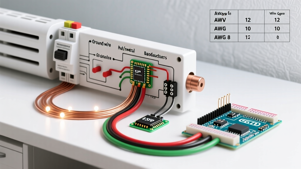
| Heater Wattage | Voltage | Amperage (Actual) | NEC 125% Sizing | Min Wire Gauge (Cu) | Breaker Size |
|---|---|---|---|---|---|
| 1000W | 240V | 4.2A | 5.25A | 12 AWG | 15A or 20A |
| 1500W | 240V | 6.25A | 7.8A | 12 AWG | 15A or 20A |
| 2000W | 240V | 8.3A | 10.4A | 12 AWG | 20A (Double Pole) |
| 2500W | 240V | 10.4A | 13.0A | 12 AWG | 20A (Double Pole) |
| 3000W | 240V | 12.5A | 15.6A | 10 AWG | 30A (Double Pole) |
Note: While 14 AWG is permissible for 15A circuits under baseline NEC rules, 12 AWG is the recommended standard for 240V heater rough-ins to ensure mechanical durability and future-proofing.
Line-Voltage Thermostats: Single-Pole vs. Double-Pole
Your wiring diagram PDF will typically offer two thermostat configurations. Understanding the safety implications of each is paramount.
- Single-Pole Thermostats (e.g., Cadet BTF1W): These interrupt only one hot leg (L1) to control the heating element. While they function correctly to turn the heat on and off, the second hot leg (L2) remains energized inside the heater junction box at all times. This presents a severe shock hazard during maintenance if the breaker is not turned off.
- Double-Pole Thermostats (e.g., King KTS-2 or Cadet BTF2W): These break both L1 and L2 simultaneously. When the thermostat is in the 'Off' position, zero voltage reaches the heating element. Many local codes, particularly in the Pacific Northwest and Canada, strictly require double-pole line-voltage thermostats for all 240V baseboard installations.
Expert Safety Warning: Never attempt to wire a 240V baseboard heater using a low-voltage (24V) smart thermostat system without installing a heavy-duty switching relay or contactor rated for the heater's specific amperage. Direct wiring will instantly destroy the smart thermostat and create a fire hazard.
Step-by-Step Physical Wiring Procedure
Translating the 240v electric baseboard heater wiring diagram PDF to the physical wall requires precision. Follow these steps for a Cadet F-Series or King K-Series unit.
1. Rough-In and Cable Preparation
Run 12/2 NM-B (Romex) cable from the double-pole 20A breaker to the heater's built-in junction box. Leave at least 8 inches of slack inside the box. Strip the outer sheathing so it enters the junction box by at least 1/4 inch, but ensure no individual wire insulation is exposed outside the cable clamp.
2. Re-Identifying the White Conductor
Because a 240V baseboard heater does not use a neutral, the white wire in your 12/2 cable will serve as the second hot leg. Per NEC 200.7(C), you must permanently re-identify this white wire at both the breaker panel and the heater junction box using black or red electrical tape, or heat-shrink tubing. Failure to do so is an immediate red flag during electrical inspections.
3. Thermostat and Element Connections
- Connect the bare copper ground wire to the green grounding screw inside the heater's junction box. Ensure a tight mechanical connection.
- Connect the black (L1) and re-identified white (L2) wires to the 'Line' terminals on your double-pole thermostat.
- Connect the two 'Load' wires from the thermostat to the two heating element leads. In a pure 240V resistive load, polarity does not matter between these two load wires.
- Torque Verification: Modern NEC 110.14(D) requires that terminals be tightened to the manufacturer's specified torque. Use an insulated torque screwdriver set to the inch-pound rating listed on the thermostat or heater schematic (typically 12-15 in-lbs for 12 AWG wire). Hand-tightening leads to loose connections, arcing, and melted wire nuts over time.
Critical Edge Cases & Failure Modes
Even with a perfect wiring diagram PDF, environmental and supply-side variables can cause system failures. Be aware of these common edge cases:
The 208V vs. 240V Mismatch
If you are installing baseboards in a multi-family dwelling, commercial space, or a home with a specific solar inverter setup, your supply voltage might be 208V (derived from a 3-phase wye system) rather than 240V. Because wattage is calculated as P = V²/R, applying 208V to a 240V-rated heater will result in a 25% drop in heat output. A 2000W heater will only produce 1500W. Always verify supply voltage with a digital multimeter before purchasing heaters.
Insulation and Convection Clearances
Baseboard heaters rely entirely on natural convection (the chimney effect) to move air. The wiring diagram PDF will not show you spatial clearances, but the installation manual will. Maintain a strict 12-inch clearance above the heater to any combustible materials, curtains, or furniture. Furthermore, ensure wall insulation behind the heater is not compressed against the back panel, as this can cause the internal thermal limit switch to trip repeatedly.
Frequently Asked Questions (FAQ)
Can I wire two 1500W baseboard heaters on a single 20A circuit?
Yes, but you must calculate the continuous load. Two 1500W heaters at 240V draw a combined 12.5 amps. Applying the NEC 125% continuous load rule (12.5 x 1.25) equals 15.6 amps. A 20-amp breaker and 12 AWG wire are perfectly adequate for this configuration, provided you wire the heaters in parallel, not in series.
Do 240V baseboard heaters require GFCI or AFCI protection?
Under standard NEC Article 424, fixed electric space heating equipment does not inherently require GFCI or AFCI protection unless installed in a location that specifically mandates it (such as a bathroom, which requires GFCI per Article 210.8). However, always check your local municipal amendments, as some jurisdictions have blanket AFCI requirements for all bedroom circuits, which can complicate baseboard installations due to nuisance tripping from resistive heating elements.
Why does my breaker trip immediately when the heater turns on?
If a newly installed heater trips the breaker instantly, you likely have a dead short. The most common cause is a pinched heating element wire touching the metal junction box, or a miswired single-pole thermostat where the line and load wires are crossed, bypassing the thermostat's internal switch entirely. Turn off the main breaker, disconnect the thermostat, and test for continuity between the hot legs and ground using a multimeter.