
Mastering the Wiring Diagram for White Rodgers Thermostat Installations
White-Rodgers thermostats, particularly the legendary 1F78 (non-programmable) and 1F80 (programmable) series, remain some of the most reliable HVAC control interfaces in the industry. Originally manufactured by Emerson Climate Technologies and now integrated into broader Copeland portfolios, these units rely on standard 24VAC Class 2 control circuits. Whether you are replacing a failed legacy unit or installing a new control loop, understanding the exact wiring diagram for White Rodgers thermostat configurations is critical to prevent blown fuses, damaged control boards, and inefficient system operation.
This comprehensive 2026 walkthrough provides a step-by-step installation guide, terminal breakdowns, transformer sizing mathematics, and advanced troubleshooting matrices tailored specifically for White-Rodgers control architectures.
Essential Tools and Materials for 24VAC Control Wiring
Before approaching the terminal block, ensure you have the correct materials. Using improper wire gauges or strippers is the leading cause of intermittent HVAC failures.
- Thermostat Wire: 18 AWG solid copper, 5-conductor (18/5) for standard systems, or 8-conductor (18/8) for heat pumps and dual-fuel setups. Expect to pay around $22 to $28 per 250-foot spool in 2026.
- Wire Strippers: Klein Tools 11063W or equivalent, specifically calibrated for 18-22 AWG solid wire to prevent nicking the copper core.
- Multimeter: A True-RMS multimeter (like the Fluke 117) capable of measuring AC voltage to verify the 24VAC supply at the air handler.
- Spare Fuses: 3-Amp ATO (automotive-style) blade fuses. These cost roughly $3 for a multi-pack and are essential for protecting the HVAC control board.
Decoding the White-Rodgers Terminal Block
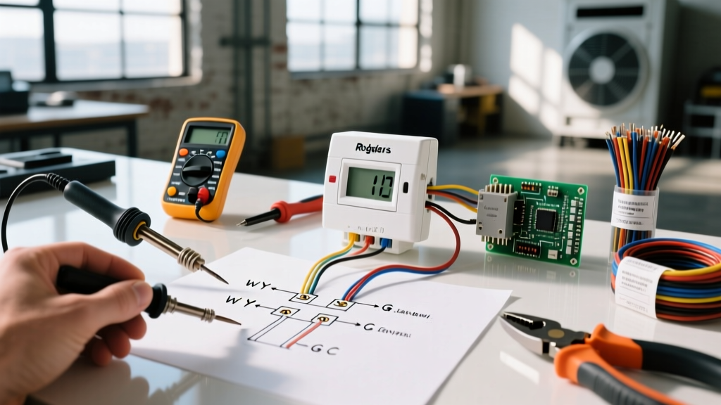
The wiring diagram for White Rodgers thermostat models revolves around a standardized color-coded terminal block. While wire colors in the field are not always strictly adhered to by previous installers, the terminal letters dictate the electrical function.
| Terminal | Function | Standard Wire Color | System Application |
|---|---|---|---|
| RC / RH | 24VAC Power (Cooling / Heating) | Red | Main power from the control transformer. Use a jumper wire between RC and RH for single-transformer systems. |
| W | Primary Heat Call | White | Engages the gas valve, ignitor, or electric heat strips. |
| Y | Cooling Compressor Call | Yellow | Energizes the contactor coil in the outdoor condenser unit. |
| G | Indoor Blower Fan | Green | Activates the indoor air handler blower relay independently of heating/cooling. |
| C | Common (24VAC Return) | Blue / Black | Completes the 24VAC circuit. Mandatory for digital displays and Wi-Fi modules. |
| O / B | Reversing Valve (Heat Pump) | Orange / Dark Blue | Switches heat pump between heating and cooling modes. Configuration depends on the outdoor unit brand. |
| E | Emergency Heat | Usually Brown or Pink | Bypasses the heat pump compressor and engages auxiliary electric resistance heat strips directly. |
Step-by-Step Wiring Walkthrough
Step 1: Power Isolation and Verification
Never rely solely on the thermostat display being blank to assume power is off. Navigate to your main electrical panel and switch off the dedicated 15A or 20A breaker for the air handler/furnace. Additionally, pull the disconnect block at the outdoor condenser unit. Use your multimeter to verify 0V across the R and C terminals at the old thermostat before removing any wires.
Step 2: Precision Wire Preparation
Strip exactly 3/8 inches (9.5mm) of insulation from each 18 AWG conductor. The terminal blocks on White-Rodgers 1F78 and 1F80 models are engineered for this exact depth. If you strip 1/2 inches or more, the exposed bare copper can easily bridge the gap between the 'R' (hot) and 'C' (common) terminals when pushed back into the wall cavity. This dead short will instantly blow the 3-amp fuse on your furnace control board.
Step 3: Backplate Mounting and Routing
Route the 18/5 wire through the center of the White-Rodgers backplate. Use a torpedo level to ensure the plate is perfectly plumb; an unlevel backplate can cause mechanical binding in older mercury-switch models or inaccurate thermal readings in digital bimetallic sensors due to improper convective airflow over the internal thermistor. Secure the backplate using the provided drywall anchors and #6 screws.
Step 4: Terminating the Conductors
Form a tight, clockwise hook with the stripped end of each wire using needle-nose pliers. Wrap the hook around the terminal screw so that tightening the screw pulls the wire loop tighter rather than pushing it out. Torque the screws until snug, but avoid over-tightening, which can strip the brass threads or shear the 18 AWG copper core.
Step 5: Jumper Configuration and Setup
For standard gas furnace and central AC combinations, your system likely uses a single 24VAC transformer. You must install a wire jumper between the RH and RC terminals to distribute power to both the heating and cooling logic circuits. If you are operating a dual-fuel system with separate transformers for the indoor and outdoor units, remove this jumper to prevent cross-phasing and catastrophic transformer failure.
Advanced Engineering: Transformer VA Sizing and Voltage Drop
A common failure point in modern HVAC retrofits is undersized control transformers. Standard HVAC control transformers are rated at 40VA (Volt-Amps). At 24VAC, this provides roughly 1.66 Amps of current. The White-Rodgers thermostat itself draws negligible current (around 0.02A for the relay coils and digital display).
However, if you are wiring a complex zoned system with multiple motorized dampers (each drawing roughly 0.1A) and an aftermarket smart Wi-Fi adapter (drawing up to 0.4A), you can easily approach or exceed the 40VA limit. When a 40VA transformer is overloaded, the voltage drops below the 20VAC minimum threshold required for the White-Rodgers logic board to hold the internal relays closed. This results in a 'chattering' relay or a blank thermostat screen when the AC kicks on. If your system requires more than 1.6A of control current, upgrade the air handler transformer to a 75VA model (approximately $35 to $45 in 2026) to ensure stable voltage delivery.
Expert Insight: When wiring the 'C' (Common) terminal, ensure it is connected to the true common side of the 24VAC transformer secondary, not a chassis ground or a 120V neutral. Connecting the thermostat 'C' wire to a 120V neutral will create a severe short circuit, potentially destroying the thermostat and tripping the main branch breaker.
Heat Pump Specifics: The 'O' vs 'B' Reversing Valve Dilemma
When utilizing the wiring diagram for White Rodgers thermostat setups on heat pumps, the most frequent error involves the reversing valve terminal. The thermostat does not dictate whether the 'O' or 'B' terminal is used; the outdoor condenser manufacturer does.
- Energize in Cooling (Wire to 'O'): Trane, Carrier, Lennox, and York typically energize the reversing valve solenoid during the cooling cycle. If the valve fails, it defaults to heating mode.
- Energize in Heating (Wire to 'B'): Rheem, Ruud, and Goodman typically energize the solenoid during the heating cycle. If the valve fails, it defaults to cooling mode.
Wiring this incorrectly will result in the system blowing cold air when you call for heat, and hot air when you call for cooling. Always verify the condenser manufacturer's schematic before terminating the orange or dark blue wire.
Troubleshooting Matrix: Common White-Rodgers Wiring Failures
| Symptom | Root Cause | Resolution |
|---|---|---|
| Completely blank digital display; no response to button presses. | Blown 3A ATO fuse on the furnace control board due to an R-C short, or missing 'C' wire connection. | Check the 3A fuse on the air handler board. Inspect thermostat wire for pinched insulation. Verify 'C' terminal continuity. |
| Thermostat clicks, but outdoor condenser does not turn on. | Broken 'Y' wire conductor inside the wall, or tripped high-pressure safety switch at the condenser. | Use a multimeter to check for 24VAC between 'Y' and 'C' at the thermostat. If present, check the contactor coil at the outdoor unit. |
| Indoor blower fan runs continuously, even when set to 'Auto'. | 'G' wire is shorted to the 'R' wire, or the HG jumper on the White-Rodgers backplate is incorrectly configured. | Separate the G and R wires. Verify the fan limit switch at the furnace plenum is not stuck in the closed position. |
| Heat pump blows cold air in heating mode. | Reversing valve wired to the wrong terminal (O instead of B, or vice versa). | Move the reversing valve wire from O to B (or B to O) based on the outdoor condenser manufacturer's specifications. |
Safety Note: Upgrading from Legacy Mercury Switch Models
If you are replacing an older White-Rodgers 1E30 series mechanical thermostat, be aware that these units contain a mercury tilt switch. Under current 2026 EPA and local environmental regulations, mercury thermostats cannot be disposed of in municipal solid waste. They must be recycled through HVAC wholesalers, local hazardous waste facilities, or the Thermostat Recovery Program (TRP). Always place the removed unit in a sealed plastic bag immediately to prevent glass breakage and toxic mercury vapor exposure.
Final Verification and System Testing
Once all wires are terminated and the White-Rodgers faceplate is snapped onto the backplate, restore power at the main electrical panel and the outdoor disconnect. Set the thermostat to 'Cool' and drop the temperature setpoint 3 degrees below the current room temperature. Listen for the distinct 'click' of the internal relay, verify the indoor blower engages, and confirm the outdoor compressor spins up within the standard 5-minute time delay. Repeat this process for the 'Heat' and 'Fan On' modes.
By strictly adhering to this wiring diagram for White Rodgers thermostat configurations and respecting the 24VAC Class 2 circuit parameters, you ensure a safe, code-compliant, and highly reliable HVAC control system.