
Decoding the Sony XAV-Series Wiring Architecture
Upgrading a factory head unit requires more than just plugging in a universal harness. When consulting a wiring diagram for Sony car stereo models—particularly the flagship XAV-AX8000, the mid-tier XAV-AX5600, or the compact XAV-AX3200—installers must account for proprietary data-bus integrations, CAN-bus wake-up signals, and specific voltage tolerances. In 2026, modern vehicles rely heavily on multiplexed data networks rather than simple 12V switched wires, making the translation between the vehicle's chassis harness and the Sony head unit's EIA-standard pigtail a critical point of failure for DIYers.
This guide provides a comprehensive, vehicle-specific breakdown of Sony head unit wiring, addressing the most common edge cases found in late-model Toyota, GM, and Ford platforms. Whether you are retaining factory amplifiers, integrating steering wheel controls (SWC), or wiring external digital signal processors (DSPs), understanding the exact pinout and logic triggers is essential for a noise-free, fully functional installation.
Universal Sony Head Unit Harness Color Matrix
Sony adheres closely to the Consumer Technology Association (CTA) and EIA standard color codes for their aftermarket pigtail harnesses. However, the functional behavior of certain wires—specifically the blue and blue/white leads—differs significantly from older legacy units. Below is the definitive reference matrix for Sony's primary power and accessory wires.
| Wire Color | Function | Voltage / Spec | Installation Notes & Edge Cases |
|---|---|---|---|
| Yellow | +12V Constant (Memory) | 12V - 14.4V DC | Connects directly to the battery or constant 12V source. Draws <5mA in standby. Must be fused within 18 inches of the battery if run direct. |
| Red | +12V Switched (Accessory) | 12V - 14.4V DC | Triggers the unit to turn on. In CAN-bus vehicles, this requires a data interface module to generate the 12V signal. |
| Black | Chassis Ground | 0V Reference | Must be secured to bare, unpainted metal. Never share a ground point with high-draw accessories like fuel pumps or inverters. |
| Blue | Power Antenna Trigger | 12V Logic (Max 300mA) | Warning: Only outputs 12V when the AM/FM tuner is active. Drops to 0V in Bluetooth, USB, or CarPlay modes. |
| Blue w/ White Stripe | Remote Amplifier Turn-On | 12V Logic (Max 300mA) | Outputs 12V continuously whenever the head unit is powered on, regardless of the active media source. Use this for amps and DSPs. |
| Orange w/ White Stripe | Illumination / Dimmer | 0V to 12V Variable | Connects to the vehicle's headlight dimmer circuit to adjust screen and button brightness. Do not connect to a constant 12V source. |
Vehicle-Specific Data Bus & Harness Integration
Modern vehicles rarely provide a simple 12V switched (Red) wire or analog illumination (Orange) wire at the radio cavity. Instead, these signals are broadcast over the vehicle's data bus. To properly execute the wiring diagram for your Sony car stereo, you must use a vehicle-specific interface module.
Toyota CAN-Bus Integration (2018-2026 Tacoma, Tundra, 4Runner)
Toyota's modern infotainment systems use a CAN-bus network to send the 'ignition on' command. If you attempt to splice the Sony Red wire into the cigarette lighter fuse, the head unit will not turn on or off in sync with the vehicle's data retention module, often leading to parasitic battery drains.
- Required Interface: Axxess TYTO-01 or Metra 70-1729 (for non-amplified) / TYTO-02 (for JBL amplified systems).
- Wiring Protocol: The interface module plugs inline with the factory 10-pin and 6-pin data connectors. It reads the CAN-bus wake-up signal and generates a clean 12V accessory output, which you then splice to the Sony harness's Red wire.
- Edge Case: On 2020+ Tundras with the factory 8-inch screen, the backup camera operates on a 6V logic signal. Sony XAV units require a 6V-to-12V step-up converter (often built into premium Axxess interfaces) to trigger the reverse wire (Purple/White) properly without frying the camera.
GM GMLAN & OnStar Retention (2016-2025 Silverado, Sierra, Tahoe)
General Motors utilizes the Class 2 GMLAN data bus. The factory radio acts as the gateway for OnStar audio prompts, door chimes, and safety alerts (like lane departure warnings). Bypassing this without a proper module will result in the loss of all vehicle warning chimes.
- Required Interface: Axxess GMOS-LAN-04 or PAC RP5-GM31.
- Wiring Protocol: The GMOS module retains the OnStar audio by routing it through the RCA pre-outs or hardwired speaker-level outputs. The Sony Blue/White remote turn-on wire must be connected to the GMOS module's 'Amp Turn-On' input to wake the internal chime amplifier.
- Door Chime Volume: Adjust the chime volume via the physical dip-switches on the GMOS-LAN-04 module before mounting the Sony unit into the dash, as software adjustment is not possible post-installation.
Ford SYNC 3 Bypass & Retention (2015-2024 F-150, Mustang)
Ford's SYNC 3 and SYNC 4 systems integrate climate controls and vehicle settings into the APIM (Accessory Protocol Interface Module). Removing the factory screen breaks the LIN-bus communication loop.
- Required Interface: Metra XSV-9003-01 or PAC RP4-FD11.
- Wiring Protocol: These modules simulate the factory radio's presence on the MS-CAN and HS-CAN networks. The Sony harness's Red (Accessory) and Yellow (Constant) wires will connect to the output side of the Metra module, which safely steps down and regulates the vehicle's smart-junction-box power.
The "Blue Wire" Trap: Amplifier & DSP Turn-On Failures
One of the most frequently misdiagnosed issues in mobile electronics occurs when installers misinterpret the Sony wiring diagram's blue leads. The Sony harness features two distinct blue wires: a solid Blue wire and a Blue wire with a White stripe.
Expert Rule of Thumb: Never use the solid Blue wire to trigger an external amplifier, DSP, or line output converter (LOC). The solid Blue wire is strictly a logic trigger for motorized power antennas and will drop to 0V the moment you switch from the AM/FM tuner to Apple CarPlay, Android Auto, or Bluetooth.
The Fix: Always connect the remote turn-on lead of your external amplifiers (such as a JL Audio VX800/8i or an AudioControl D-6.1200) to the Blue/White stripe wire on the Sony harness. This wire provides a continuous 12V, 300mA logic signal across all media sources. If your amplifier requires more than 300mA to trigger (common with multiple stacked amplifiers), use the Blue/White wire to trigger a 30A automotive relay, and draw the high-current switching power directly from the battery.
Steering Wheel Control (SWC) Resistance Mapping
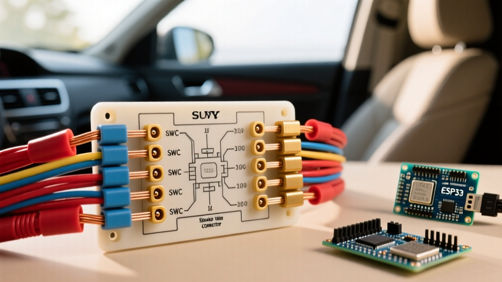
Sony XAV-series receivers utilize a standardized 3.5mm SWC input jack located on the rear chassis. Unlike older units that required splicing into a specific resistor-ladder wire, modern Sony units rely on an external SWC interface to translate the vehicle's factory steering wheel button presses into a 3.5mm analog resistance signal.
- Interface Selection: Use the Axxess ASWC-1 or PAC SWI-RC. These modules auto-detect the vehicle's data bus or analog resistance ladder.
- Wiring the 3.5mm Jack: Plug the male 3.5mm connector from the interface module directly into the Sony's SWC port. Do not use a 2.5mm adapter, as the pinout depth will cause intermittent button mapping failures.
- Mapping Sequence: Power on the Sony unit. Navigate to Settings > General > Steering Wheel Control. Select 'Preset 1'. The Sony screen will prompt you to press and hold each factory button (Volume Up, Volume Down, Seek, Mode) to map the resistance values. If a button registers as 'Error', the interface module's ground wire is likely sharing a noisy ground point; relocate it to a dedicated chassis bolt.
Multimeter Validation & Grounding Protocols
Before finalizing the dash assembly, validate your wiring using a digital multimeter (DMM) such as the Fluke 115 or Fluke 87V. Relying on a simple 12V test light is insufficient for modern digital head units, as test lights cannot detect voltage drop or high-frequency alternator whine.
- Voltage Drop Testing: Set your DMM to DC Volts. Place the red probe on the battery's positive terminal and the black probe on the Sony unit's Yellow wire at the harness connection. With the unit powered on, the reading should not exceed 0.2V. If it reads higher, your power wire gauge is too thin or you have a corroded fuse holder.
- Ground Integrity: Place the red probe on the battery's negative terminal and the black probe on the Sony Black ground wire. A reading above 0.1V indicates a poor chassis ground. Scrape away paint, use a star washer, and apply dielectric grease to the connection point to prevent galvanic corrosion.
- Pre-Out Voltage Check: If using the Sony XAV-AX5600, verify the RCA pre-outs. This model features high-voltage 5V pre-outs (compared to the standard 2V on budget models). Ensure your external amplifier's input sensitivity gain is turned all the way down before the initial power-on to prevent clipping and blowing your tweeters.
Authoritative References
For further technical specifications, vehicle fitment data, and safety protocols, consult the following industry resources:
- Crutchfield Car Stereo Installation Guide - Comprehensive tutorials on dash disassembly, wiring harness identification, and SWC integration.
- Metra Electronics Vehicle Fitment Database - The definitive resource for identifying the correct CAN-bus interface modules and dash kits for specific make/model/year vehicles.
- Sony Electronics Car Audio Support Hub - Official firmware updates, wiring PDF schematics, and troubleshooting guides for the XAV-AX series receivers.