
The Anatomy of a Fuel Gauge Circuit
When your dashboard fuel needle drops to empty while the tank is full, or bounces erratically over every bump, the culprit is rarely a bad gauge itself. More often, the failure lies within the sender unit, the wiring harness, or the instrument voltage regulator. Even in 2026, as CAN-bus networks and digital telemetry dominate modern EVs and hybrids, thousands of classic cars, marine vessels, agricultural tractors, and off-grid generators still rely on analog 12V variable-resistance sender circuits. To diagnose these systems efficiently, you must understand how to read a wiring diagram for a fuel gauge and translate its symbols into real-world multimeter tests.
At its core, an analog fuel gauge circuit is a simple series loop consisting of four main components:
- Power Source: Typically a 12V switched ignition feed.
- Instrument Voltage Regulator (IVR): Steps down and pulses the 12V battery voltage to a stable 5V to 7V average to prevent gauge fluctuations as the alternator output varies.
- The Gauge (Galvanometer): Contains electromagnetic coils that move the needle based on the current flowing through the circuit.
- The Sender Unit: A variable resistor (potentiometer) attached to a float arm inside the fuel tank. As the fuel level changes, the resistance changes, altering the current flow and moving the needle.
Decoding the Wiring Diagram for a Fuel Gauge
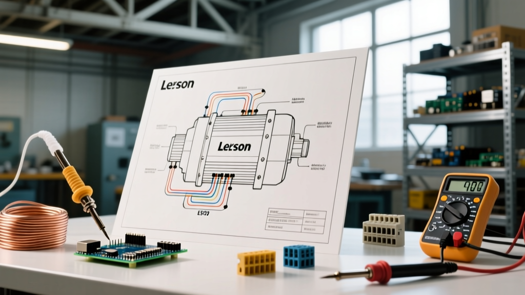
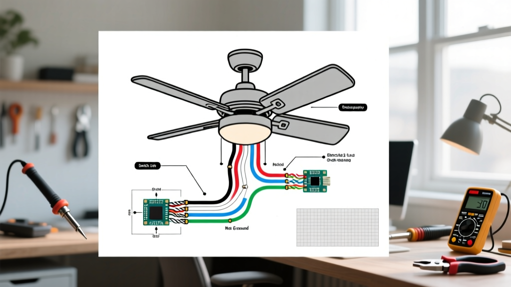
When you pull up a factory service manual or an aftermarket diagram from brands like Stewart Warner or VDO, you will notice the sender unit is represented by a standard resistor symbol with an arrow striking through it, indicating a variable resistance. The wire connecting the gauge to the sender is usually labeled as the Signal or Sender wire (often colored dark green, purple, or yellow depending on the manufacturer).
The Golden Rule of Gauge Diagnostics: The gauge needle is simply a visual representation of the resistance to ground on the signal wire. If you understand whether your specific system uses a 'high-resistance-full' or 'low-resistance-full' logic, you can diagnose 90% of faults without ever dropping the fuel tank.
2-Wire vs. 3-Wire Sender Configurations
Most automotive applications use a 1-wire signal system where the sender's ground is achieved through the physical metal tank and chassis (making it a 2-wire circuit total: Signal + Ground). However, marine environments and fiberglass-bodied vehicles require a 3-wire sender. The wiring diagram for a 3-wire fuel gauge will show a dedicated ground wire running from the sender flange back to the chassis or battery negative, alongside the signal wire and a separate power feed for integrated low-fuel warning switches.
The Ohm Matrix: Matching Your Sender to Your Gauge
The most common mistake DIYers make is pairing a gauge with an incompatible sender. If your wiring is perfect but the needle reads backward or only moves halfway, you have an ohm-range mismatch. According to AA1Car's comprehensive fuel gauge diagnostic library, verifying the ohm range is the mandatory first step before replacing any parts.
| Manufacturer / Standard | Empty (Ohms) | Full (Ohms) | Common Applications |
|---|---|---|---|
| GM (General Motors) | 0 Ω | 90 Ω | Classic GM cars, trucks up to early 2000s |
| Ford | 16 Ω | 158 Ω | Most Ford vehicles from the 1960s through 1980s |
| Chrysler / Mopar | 73 Ω | 10 Ω | Classic Chrysler, Dodge, Plymouth |
| VDO (European) | 10 Ω | 180 Ω | BMW, Mercedes, VW, aftermarket Euro gauges |
| Stewart Warner | 33 Ω | 240 Ω | Heavy duty, marine, universal aftermarket |
| Standard Aftermarket | 240 Ω | 33 Ω | Many modern universal marine and RV gauges |
Step-by-Step Multimeter Troubleshooting
To execute these tests, you will need a reliable Digital Multimeter (DMM) with a resolution of at least 0.1 ohms. A tool like the Fluke 117 (retailing around $190 in 2026) is ideal due to its True-RMS capabilities and low-impedance AutoV mode, which prevents ghost voltage readings on long harness runs. For a deeper dive into proper meter usage, reference Fluke's official resistance measurement guide.
Step 1: The 'Jumper to Ground' Test
This test isolates the dashboard circuit from the fuel tank.
- Turn the ignition to the 'ON' position (engine off).
- Locate the sender wire at the fuel tank (usually a single spade terminal on the sender flange).
- Disconnect the wire and momentarily jumper the harness side (the wire going back to the dash) directly to a clean chassis ground.
- Observe the gauge: If you have a GM (0-90Ω) system, grounding the wire simulates 0 ohms, so the needle should slam to Empty. If you have a Stewart Warner (240-33Ω) system, grounding the wire simulates 0 ohms, which is off the scale low, so the needle will peg past Full. If the gauge responds correctly, your dash wiring, IVR, and gauge are perfect. The fault is in the tank.
Step 2: Testing the Sender Resistance
If Step 1 proved the dash is functional, the issue is in the tank. Set your DMM to the Ohms (Ω) setting.
- Disconnect the signal wire from the sender.
- Place your red probe on the sender's signal terminal and your black probe on a known good chassis ground (or the dedicated ground wire on a 3-wire marine sender).
- Have an assistant watch the gauge or use a mirror. If the tank is full, a GM sender should read close to 90Ω. If it reads infinite (OL), the internal wiper track is broken or the float arm has snapped off the pivot.
Step 3: Simulating the Sender with a Decade Box
For professional-level diagnostics without dropping the tank, connect a Decade Resistance Box between the signal wire and ground. Dial in the 'Full' resistance value for your specific system (e.g., 240Ω for SW). If the gauge reads exactly Full, your wiring harness has perfect continuity and zero voltage drop. If it reads low, you have high resistance in the copper wiring or corroded bulkhead connectors.
Bypassing a Faulty Instrument Voltage Regulator (IVR)
A frequently overlooked component in the wiring diagram is the IVR. Older mechanical IVRs use a bimetallic strip that physically opens and closes to pulse voltage. Over time, the contacts pit and corrode, causing the average voltage to drop from 6V down to 3V, resulting in gauges that read consistently low or sluggish.
The Fix: You can bypass a failing mechanical IVR by installing a solid-state electronic IVR (such as those made by Instrument Specialties or custom 7805-based DIY circuits). These solid-state units output a dead-steady 5.0V DC without pulsing, eliminating the 'ticking' sound behind the dash and providing pinpoint gauge accuracy. When modifying the diagram for a solid-state swap, ensure you wire the 12V input to the ignition switch and the 5V output directly to the 'I' or 'B+' terminal on the back of the fuel gauge.
Real-World Edge Cases & Grounding Gremlins
In marine applications and older 4x4s, the most common failure mode isn't a broken wire, but a corroded ground path. Because a 1-wire sender relies on the fuel tank mounting straps to complete the circuit to the chassis, rust between the tank and the strap introduces resistance into the circuit.
For example, if your GM sender reads 90Ω (Full), but there is 15Ω of rust resistance on the tank strap ground, the gauge sees 105Ω. On a sensitive galvanometer, this extra resistance will cause the needle to peg past Full or trigger the over-voltage stop. Always run a dedicated 14 AWG copper ground wire from the sender flange directly to the chassis, bypassing the tank straps entirely. This single $2 modification solves roughly 40% of all 'erratic fuel gauge' complaints in restoration shops.
Frequently Asked Questions
Why does my fuel gauge read full when the key is off?
This indicates a back-feed of voltage into the gauge circuit, usually caused by a short between the fuel gauge signal wire and a constant 12V source (like a tail light or radio memory wire) inside a damaged wiring harness. Consult your wiring diagram to trace the harness routing through the firewall and kick panels.
Can I use a standard 12V dimmer switch to test a fuel gauge?
No. Fuel gauges react to resistance, not just voltage. A dimmer switch alters voltage via PWM or variable resistance, but it cannot accurately simulate the specific ohm curves required by the gauge's internal coils. Always use precision resistors or a decade box.
My gauge needle bounces wildly when driving. Is the sender bad?
While a worn wiper track inside the sender can cause bouncing, this is more commonly caused by a failing mechanical Instrument Voltage Regulator (IVR) that is sticking, or sloshing fuel in a tank missing its internal anti-slosh baffles. Check the IVR output with a multimeter set to Min/Max mode before condemning the sender.