
Introduction: Upgrading the GMT800 Platform Safely in 2026
The 1999 Chevy Silverado marked the debut of General Motors' legendary GMT800 platform. While these trucks are renowned for their mechanical longevity, their electrical systems require careful handling when integrating modern electronics. As of 2026, aftermarket head units featuring wireless CarPlay, Android Auto, and integrated DSP amplifiers draw significantly more current and generate more electromagnetic interference (EMI) than the original Delco AM/FM cassette decks. Understanding the exact radio wiring diagram for 1999 Chevy Silverado models is not just about making the stereo work; it is about adhering to automotive electrical safety standards, preventing catastrophic module failures, and ensuring fire-safe wire splicing.
This guide approaches the 1999 Silverado stereo installation from a strict safety and code compliance perspective, referencing SAE International J1128 standards for low-tension primary cable and IPC J-STD-001 requirements for soldered electrical assemblies.
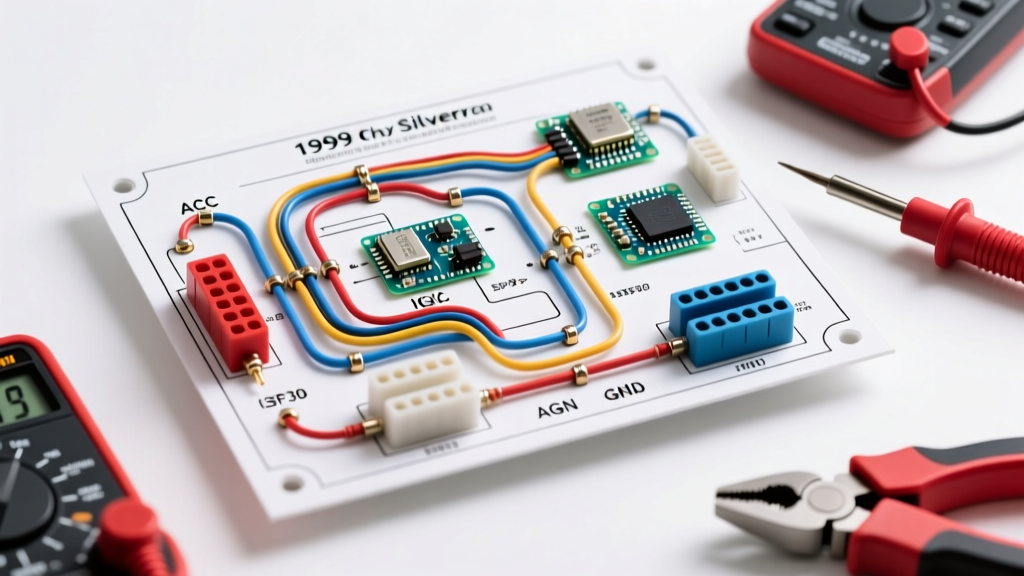
1999 Chevy Silverado Radio Wiring Diagram: Color Codes & Specifications
The standard 1999 Silverado (without the premium Bose amplified system) utilizes a standard GM 16-pin or 24-pin harness. When using a compliant adapter like the Metra 70-1857, you will interface with the following color-coded circuit. Always verify with a digital multimeter (DMM) before making connections, as 25 years of dealership repairs can result in non-standard wire swaps.
| Wire Color | Function | Standard Gauge | Max Fuse Rating |
|---|---|---|---|
| Yellow | Battery Constant 12V+ (Memory) | 18 AWG | 15A |
| Red | Ignition Switched 12V+ (Accessory) | 18 AWG | 10A |
| Black | Chassis Ground | 18 AWG | N/A |
| Gray | Right Front Speaker (+) | 20 AWG | N/A |
| Gray w/ Black Stripe | Right Front Speaker (-) | 20 AWG | N/A |
| White | Left Front Speaker (+) | 20 AWG | N/A |
| White w/ Black Stripe | Left Front Speaker (-) | 20 AWG | N/A |
| Purple | Right Rear Speaker (+) | 20 AWG | N/A |
| Purple w/ Black Stripe | Right Rear Speaker (-) | 20 AWG | N/A |
| Green | Left Rear Speaker (+) | 20 AWG | N/A |
| Green w/ Black Stripe | Left Rear Speaker (-) | 20 AWG | N/A |
| Brown | Illumination (Dash Lights) | 22 AWG | 5A |
| Orange | Dimmer / Class 2 Data (CAUTION) | 22 AWG | 3A |
Critical Safety Warning: The Class 2 Serial Data Line Trap
The most severe compliance and safety risk when wiring a 1999 Silverado radio involves the Orange wire. In many older GM vehicles, the orange wire is simply a dash dimmer circuit. However, in the GMT800 architecture, the orange wire in the primary dash harness often carries the Class 2 Serial Data signal. This is the low-voltage communication network that allows the Body Control Module (BCM), Powertrain Control Module (PCM), and instrument cluster to talk to one another.
HAZARD ALERT: Never splice into, tap, or ground the Orange wire on a 1999-2002 Silverado without verifying its function with an oscilloscope or factory service manual. Accidentally grounding the Class 2 data line or feeding 12V into it will instantly short the BCM. A replacement BCM and dealership reflashing procedure will cost upwards of $450 to $600 in 2026. If your aftermarket head unit requires an illumination or dimmer wire, safely cap the vehicle's orange wire and use the Brown wire for illumination, or leave the dimmer function disconnected.
While automotive low-voltage data lines are not strictly governed by the NFPA 70 National Electrical Code (NEC) Article 725 (which covers Class 2 and Class 3 circuits in buildings), the underlying physics of isolating sensitive data lines from high-current DC power lines remains identical. Keep your speaker wires and 12V constant/switched lines routed at least 2 inches away from any retained factory data harnesses to prevent inductive EMI coupling.
Code-Compliant Wire Splicing: IPC J-STD-001 Standards
Amateur installers frequently rely on 'Scotchlok' T-tap connectors or cheap twist-crimps. From a safety and code compliance perspective, these are unacceptable for permanent automotive installations. T-taps pierce wire insulation, exposing bare copper to humidity and road salt, leading to micro-arcing, high resistance, and eventual localized melting. Instead, professional installers adhere to IPC J-STD-001 soldering standards and SAE J1128 insulation requirements.
The Proper Solder and Heat-Shrink Protocol
- Strip and Interlock: Strip exactly 3/8 inch of insulation from both the harness wire and the adapter wire. Twist the exposed copper strands together in an interlocking 'X' pattern to ensure mechanical strength before the solder even flows.
- Apply Flux and Solder: Use rosin-core solder (60/40 or lead-free SAC305). Apply heat to the copper wire, not the solder itself. Capillary action should draw the solder completely through the twisted joint. The joint must appear shiny and smooth; a dull, grainy appearance indicates a 'cold joint' which will vibrate apart under the Silverado's chassis harmonics.
- Adhesive-Lined Heat Shrink: Slide 3M MDT or Ancor Marine adhesive-lined polyolefin heat shrink over the joint. This specific material features an inner layer of thermoplastic adhesive that melts and seals out moisture and oxidation. Apply heat evenly until the adhesive extrudes slightly from both ends of the tubing.
Grounding Protocols and Alternator Whine Prevention
A common failure mode in GMT800 audio upgrades is alternator whine—a high-pitched noise that revs with the engine. This is caused by a ground loop, which occurs when the radio's ground path and the amplifier's ground path have different resistance levels, causing current to flow through the RCA shield cables.
Code-Compliant Grounding Steps:
- Location: Do not ground the radio to the thin sheet metal of the dash support bracket. Locate a heavy, unpainted steel bolt that threads directly into the main chassis or firewall.
- Preparation: Use a wire brush or sandpaper to remove all paint, clear coat, and rust down to bare, shiny metal. Paint acts as a dielectric insulator and will force the ground current to seek alternate, noisy paths.
- Termination: Crimp a closed-ring terminal (not a spade terminal) onto the black ground wire. Secure it tightly with a star washer to bite into the metal and prevent vibration loosening.
- Corrosion Protection: Coat the finished ground connection with dielectric grease or a dedicated battery terminal protector to prevent galvanic corrosion over time.
Troubleshooting Matrix: Common GMT800 Audio Failures
| Symptom | Root Cause | Code-Compliant Corrective Action |
|---|---|---|
| Radio loses memory/presets every time the truck is turned off. | Yellow (Constant 12V) and Red (Switched 12V) wires are swapped at the harness adapter. | Verify with a DMM. The Yellow wire must read 12V with the key completely removed from the ignition. |
| Radio turns on, but no sound from speakers; 'LOC' may appear on factory deck. | Factory Theftlock anti-theft feature is engaged, or aftermarket harness is missing the Class 2 data wake-up signal. | If using an aftermarket unit, ensure the Metra 70-1857 is fully seated. If retaining factory, perform the Theftlock reset procedure via the owner's manual. |
| Alternator whine that changes pitch with engine RPM. | Ground loop due to poor chassis grounding or RCA cables routed parallel to power wires. | Re-terminate ground to bare chassis metal. Re-route RCA cables down the opposite side of the vehicle's center console from the 12V power wire. |
| Truck battery drains overnight (parasitic draw). | Aftermarket radio's internal amplifier is not shutting down due to improper ignition wire tapping. | Ensure the Red wire is tied strictly to an ignition-switched source, not a retained accessory power (RAP) circuit that stays live for 10 minutes after door opening. |
Frequently Asked Questions
Do I need to disconnect the battery before wiring the radio?
Yes. Under SAE and general automotive safety protocols, you must disconnect the negative battery terminal before cutting, stripping, or soldering any wires in the GMT800 dash. The 1999 Silverado's airbag system (SIR) utilizes yellow-jacketed wiring under the dash; accidentally shorting a 12V source to an SIR circuit can cause accidental deployment or blow the $300+ SIR diagnostic module.
Can I use the factory antenna cable with a 2026 aftermarket head unit?
The 1999 Silverado uses a standard Motorola (DIN) antenna plug. However, the cable routing from the fender well to the dash is quite long, and the factory shielding often degrades after two decades. If you experience poor AM/FM reception, replace the entire mast and cable assembly rather than using a signal booster, which will only amplify EMI noise.
What if my 1999 Silverado has the premium Bose system?
If your truck is equipped with the factory Bose amplifier, the standard wiring diagram above will not work directly. The Bose system uses low-level differential audio signals and a dedicated amplifier turn-on wire. You must use a specialized line-output converter (LOC) or a premium integration harness (like the Axxess GMOS-04) to safely step down the signals and interface with the factory amp without causing clipping or thermal overload.