
Decoding the Wiring Diagram for Whirlpool Washing Machine Models
Modern laundry appliance repair relies heavily on accurate schematic interpretation. When dealing with the ubiquitous Vertical Modular (VM) platform—which powers millions of Whirlpool, Maytag, Roper, and Admiral top-load washers—understanding the wiring diagram for Whirlpool washing machine circuits is the difference between a $25 DIY fix and a $300 service call. Models like the Whirlpool WTW4816FW, WTW5000DW, and Maytag MVWC565FW all share similar VM electrical architectures, utilizing a centralized main control board, a shift actuator, and a capacitor-start drive motor.
This reference guide breaks down how to locate, read, and apply the factory tech sheet to diagnose electrical faults, complete with exact multimeter resistance values and wire color decoding.
Locating the Factory Tech Sheet and Schematic
Before you can trace a circuit, you need the correct schematic. Whirlpool does not expect technicians to memorize these diagrams; instead, they include a 'Tech Sheet' with every unit.
- Behind the Console: On most VM washers, you will find a plastic zip-lock bag taped to the underside of the top console panel or the backguard. This contains the wiring diagram, error code chart, and diagnostic mode instructions.
- Inside the Front Panel: On some newer 2024-2026 iterations, the tech sheet is tucked into a plastic sleeve mounted to the inner front panel, accessible by popping the two hidden clips at the rear of the top cover and lifting it.
- Lower Access Panel: Occasionally, the schematic is taped to the inside of the lower front access panel near the drain pump.
Pro-Tip: Never rely on a generic wiring diagram downloaded from a third-party forum. Whirlpool frequently updates control board firmware and harness pinouts mid-production run. Always use the physical tech sheet shipped inside your specific serial number's cabinet.
Whirlpool Wire Color Code Matrix
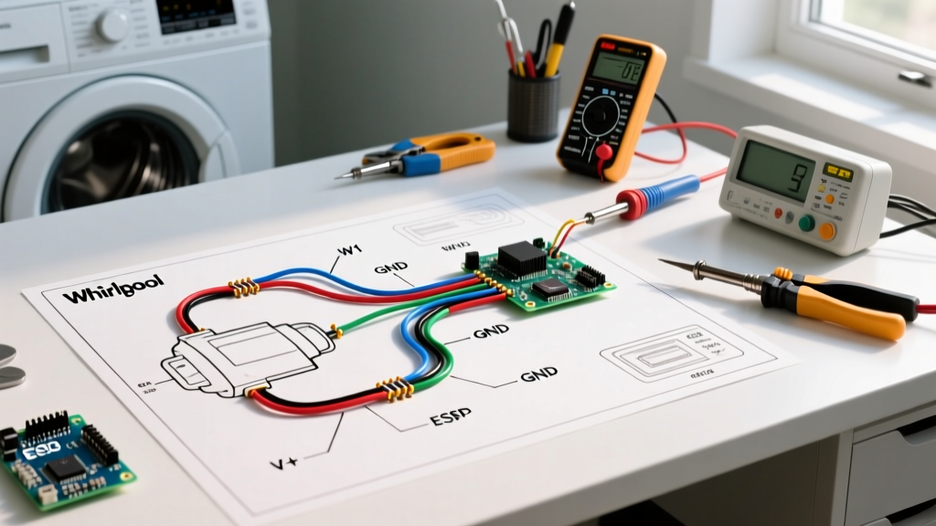
One of the most confusing aspects for beginners reading a Whirlpool schematic is the wire color abbreviation system. The wiring diagram for Whirlpool washing machine harnesses uses standardized two-letter codes rather than full color names. If you misread 'BU' as 'Brown' instead of 'Blue', you will send 120V directly into a low-voltage logic circuit, instantly destroying the main control board.
| Abbreviation | Actual Wire Color | Typical Circuit Function |
|---|---|---|
| BK | Black | 120V AC Line (Hot) or High-Voltage Motor Feed |
| WH | White | 120V AC Neutral or Common Return |
| BU | Blue | Switched Line, Lid Lock Solenoid, or Valve Feed |
| RD | Red | Secondary Motor Winding, Pump Hot, or Sensor 5V |
| V | Violet | Tachometer Signal, Optical Sensor, or Data Line |
| OR | Orange | Shift Actuator Motor or Agitate/Spin Sense |
| GY | Gray | Neutral Sense or Secondary Switch Return |
| GN | Green | Chassis Ground (Earth) |
Core Component Testing via the Wiring Diagram
Using the schematic, you can isolate components from the main control board and test them directly at the harness connectors. Below are the exact resistance specifications for the most commonly failed VM platform components.
1. The Lid Lock Assembly (e.g., Part #W11307244)
The lid lock contains three distinct circuits mapped on the wiring diagram: the solenoid (lock/unlock), the lock sense switch, and the lid open/closed switch.
- Solenoid Coil: Test across the Blue (BU) and White (WH) wires at the lock. Expected resistance: 65 to 75 ohms. If it reads infinite (OL), the coil is burnt out, usually due to a jammed locking striker forcing the solenoid to overheat.
- Lock Sense Switch: Test across the Red (RD) and White (WH) wires. Should read 0 ohms (continuity) when manually locked, and OL (open) when unlocked.
2. Shift Actuator (e.g., Part #W10721967)
The shift actuator is a small gearmotor with an optical encoder that physically moves the splutch (splined clutch) to engage either the agitator dogs or the spin basket. The wiring diagram shows a 5-pin or 6-pin connector.
- Actuator Motor: Test across the two main power pins (usually Orange and Red). Expected resistance: 1.2k to 1.8k ohms.
- Optical Sensor: This cannot be accurately tested for resistance with a standard multimeter. You must enter the washer's manual diagnostic mode to observe the 'Sensing' LED flashing as you manually rotate the actuator cam.
3. Drive Motor and Capacitor (e.g., Part #W11158830)
Modern VM washers use a Permanent Split Capacitor (PSC) or Capacitor-Start induction motor. The wiring diagram routes power from the main board, through a 35-45 microfarad capacitor, to the motor windings.
- Motor Windings: Disconnect the harness. Test between the Blue (BU) and Red (RD) pins on the motor housing. Expected resistance: 10 to 15 ohms. Test between Blue (BU) and White (WH). Expected resistance: 10 to 15 ohms. If any reading is below 5 ohms, the windings are shorted, and the motor must be replaced.
Step-by-Step Troubleshooting: Washer Fails to Spin
Let us apply the wiring diagram to a real-world failure mode: The washer agitates fine, fills and drains, but refuses to enter the high-speed spin cycle, often throwing an F7-E1 (Basket Speed) or F7-E5 (Motor Fault) error code.
- Verify the Splutch and Actuator: According to the schematic, the main board sends 120V AC down the Orange (OR) wire to the shift actuator. If the actuator receives voltage but fails to move the cam, the mechanical splutch is jammed. If the actuator receives zero voltage, trace the Orange wire back to the main control board relay.
- Check the Tachometer Circuit: The main board relies on a tachometer signal to know the motor is spinning. The wiring diagram routes this low-voltage signal via the Violet (V) and Gray (GY) wires from the motor sensor to the board. A broken Violet wire will cause the board to assume the motor is stalled, cutting power after 3 seconds to prevent a fire.
- Inspect the Capacitor: A weak capacitor will provide enough phase-shift to start the low-torque agitate cycle, but fail under the heavy load of the spin cycle. Discharge the capacitor safely with a 20k-ohm resistor, then test with a multimeter's capacitance setting. A 35µF capacitor reading below 30µF is defective.
Electrical Safety and NEC Compliance
When interpreting the wiring diagram for Whirlpool washing machine installations, you must also consider the supply circuit. According to the National Fire Protection Association (NFPA) and the National Electrical Code (NEC), laundry areas have strict safety mandates. NEC Article 210.8(A)(11) strictly requires GFCI (Ground-Fault Circuit Interrupter) protection for all 125-volt through 250-volt receptacles supplied by single-phase branch circuits rated 150 volts or less to ground in laundry areas.
Furthermore, the washer must be on a dedicated 20-amp branch circuit using a minimum of 12 AWG copper wire. If your washing machine frequently trips the GFCI breaker, do not bypass the safety device. Instead, use the wiring diagram to check for a ground fault in the water inlet valves or the drain pump motor, as moisture intrusion in these components is the leading cause of nuisance GFCI tripping in 2026. For more on appliance electrical safety standards, refer to the U.S. Consumer Product Safety Commission (CPSC) Electrical Safety Guidelines and the NFPA 70 National Electrical Code.
Frequently Asked Questions
Can I run the washer with the wiring diagram tech sheet removed?
Yes, the tech sheet is purely for reference and does not affect the electrical circuit. However, you should tape it back inside the cabinet. Future technicians, or yourself in five years, will need it for accurate troubleshooting.
Why does the wiring diagram show a 'Neutral Sense' circuit?
Modern Whirlpool main control boards feature a 'Neutral Sense' circuit (often utilizing a Gray wire). This allows the microprocessor to verify that the incoming wall receptacle is wired correctly and that the neutral path is intact before closing the main motor relay. If the board cannot detect a valid neutral, it will lock out the high-voltage components to prevent electrical shock hazards.
Where can I find official replacement schematics?
If your physical tech sheet is missing or degraded, you can download official PDF service manuals and wiring diagrams directly through the Whirlpool Official Support Portal by entering your exact model and serial number.