
Understanding Kitchen Circuit Requirements for Disposals
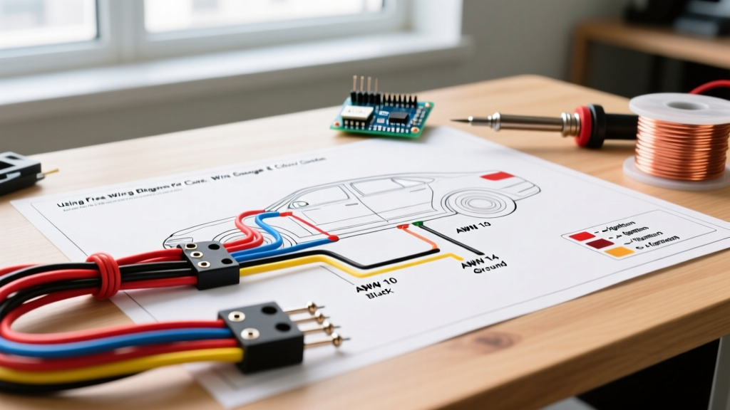
When planning a kitchen remodel or replacing a failed unit, interpreting a wiring diagram for garbage disposal systems is a critical skill for any DIYer or apprentice electrician. Modern kitchens demand rigorous adherence to the National Electrical Code (NEC), particularly regarding Ground Fault Circuit Interrupter (GFCI) and Arc Fault Circuit Interrupter (AFCI) protections. According to the National Fire Protection Association (NFPA), kitchen appliance circuits must be properly sized to handle the inductive motor loads of disposals without nuisance tripping.
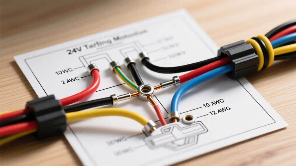
Before touching a single wire, you must verify your circuit's amperage and wire gauge. Most standard 1/2 HP to 3/4 HP disposals (like the InSinkErator Badger 5 or Evolution Compact) draw between 6.0 and 8.5 amps. However, heavy-duty 1 HP models (such as the Waste King L-8000 or Moen EXL100) can pull up to 10 amps on startup. Always match your wire gauge to the breaker size, never the appliance draw alone.
Wire Gauge and Breaker Sizing Matrix
| Breaker Size | Wire Gauge (NM-B) | Max Continuous Load | Typical Disposal HP |
|---|---|---|---|
| 15 Amp Single-Pole | 14 AWG (14/2) | 12 Amps (1440W) | 1/3 HP to 3/4 HP |
| 20 Amp Single-Pole | 12 AWG (12/2) | 16 Amps (1920W) | 3/4 HP to 1 HP+ |
Pro Tip: If your disposal shares a circuit with a dishwasher, you must use a 20-amp breaker with 12/2 NM-B Romex wire. The combined running load of a dishwasher heating element (often 10-12 amps) and a disposal motor (6-8 amps) will easily exceed the 15-amp continuous limit, causing thermal breaker fatigue over time.
Decoding the Wiring Diagram for Garbage Disposal Units
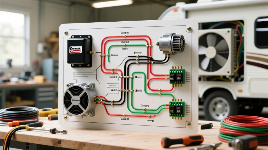
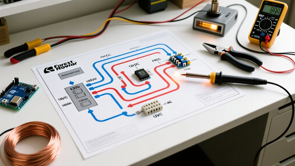
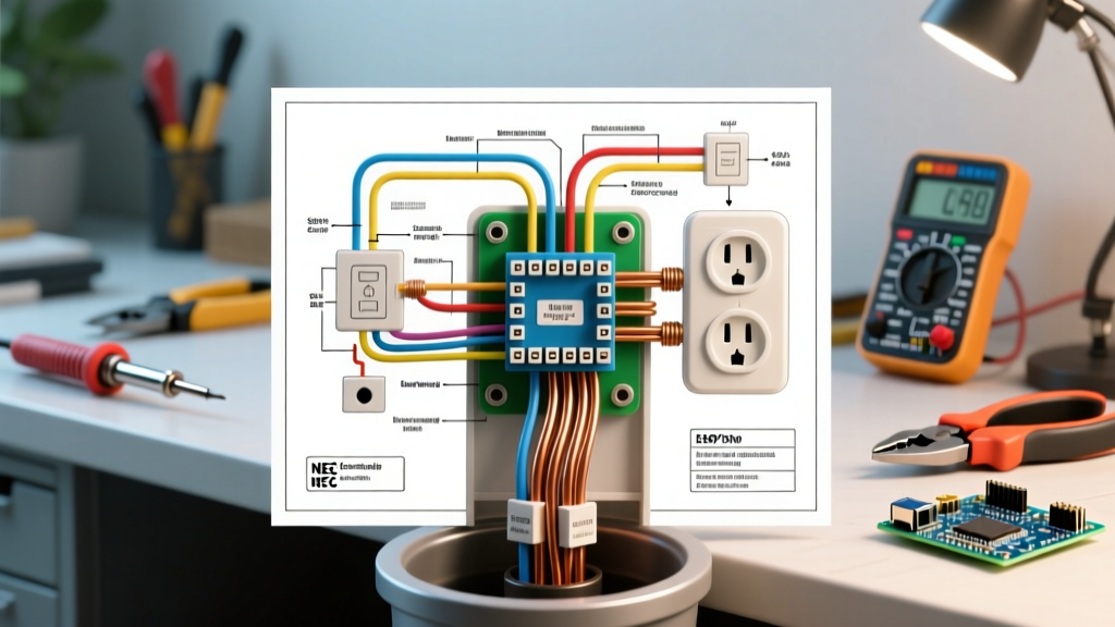
There are two primary ways to wire a kitchen disposal: a dedicated hardwired switch loop or a shared split-receptacle under the sink. Your specific wiring diagram for garbage disposal installation will depend entirely on which of these two configurations your kitchen utilizes.
Scenario A: Hardwired Disposal with a Wall Switch
In this configuration, the disposal is hardwired directly into an electrical box under the sink, and power is routed through a single-pole wall switch. This is the cleanest, most reliable method and eliminates the risk of a plug vibrating loose due to motor torque.
- Power Feed to Switch: Run 14/2 or 12/2 NM-B cable from your main panel (or upstream junction) to the wall switch box. Connect the bare copper to the green ground screw, the white neutral to the neutral bundle (using a Wago 221 lever nut), and the black hot wire to the bottom brass terminal on the switch.
- Switch Leg to Disposal: Run a second cable from the switch box to the disposal junction box under the sink. Connect the white wire to the neutral bundle, and the bare copper to the ground.
- The Hot Connection: Connect the black wire from the switch leg to the black (hot) wire on the disposal. Note: In standard switch loops, the white wire in the second cable is often used as a hot return. If your diagram dictates this, wrap black electrical tape around both ends of the white wire to re-identify it as a hot conductor, per NEC Article 200.7.
- Finalizing the Disposal Box: Secure the Romex with a 3/8-inch non-metallic cable clamp. Strip exactly 3/4 inch of insulation from the conductors using Klein Tools 11055 strippers to ensure no bare copper is exposed outside the wire nut.
Scenario B: Split-Receptacle for Disposal and Dishwasher
Many modern homes utilize a split-wired duplex receptacle under the sink. The top half is switched (for the disposal), and the bottom half is always hot (for the dishwasher). This requires a specific wiring diagram for garbage disposal and dishwasher sharing.
- Break the Brass Tab: Take a Leviton 5262 (15A) or 5362 (20A) duplex receptacle. Using needle-nose pliers, snap off the small brass connecting tab on the hot (shorter slot) side. Do not break the silver tab on the neutral side, as both appliances share a common neutral return.
- Switched Hot (Top): Connect the black wire coming from your wall switch to the top brass screw. Plug the disposal's cord into the top receptacle.
- Constant Hot (Bottom): Connect the black wire from your always-on power feed to the bottom brass screw. Plug the dishwasher into the bottom receptacle.
- Shared Neutral & Ground: Pigtail the white neutral wires from both feeds together with the receptacle's silver screw. Pigtail all bare ground wires to the green grounding screw.
Hardwired vs. Cord-and-Plug: Which is Better?
When reviewing your wiring diagram for garbage disposal setups, you must decide between hardwiring and using a cord-and-plug. While hardwiring is traditional, the 2023 and upcoming 2026 NEC updates heavily favor plug-in configurations for serviceability.
Hardwired Pros: No receptacle required (saves $5-$10); zero risk of plug vibration; cleaner look under the sink.
Hardwired Cons: Requires opening the disposal's internal junction box for replacement; higher shock risk during unit swaps.
Cord-and-Plug Pros: Instant disconnect for maintenance; complies easily with modern GFCI receptacle requirements; easier for DIY replacement.
Cord-and-Plug Cons: Requires an under-sink receptacle; cords can occasionally vibrate loose if not secured with a cord grip.
For 2026 installations, we strongly recommend the cord-and-plug method paired with a GFCI-protected split receptacle. The U.S. Consumer Product Safety Commission (CPSC) consistently highlights that accessible disconnects and GFCI protection drastically reduce electrocution hazards in damp under-sink environments.
Common Wiring Mistakes and Troubleshooting
Even with a perfect wiring diagram for garbage disposal circuits, field errors occur. Here are the most common failure modes and how to diagnose them:
1. The GFCI Nuisance Trip
If your disposal trips the GFCI receptacle immediately upon startup, the issue is rarely the wiring diagram itself. Disposal motors generate significant inductive back-EMF (electromotive force) when starting. If the GFCI is an older model, it may misinterpret this inductive spike as a ground fault. Solution: Upgrade to a modern GFCI receptacle (like the Leviton GFNT2) designed with advanced microprocessors that filter out motor-induced inductive noise.
2. Humming Without Rotation
If the motor hums but the flywheel does not spin, do not assume an electrical wiring failure. This is a mechanical jam. Solution: Turn off the breaker. Insert a 1/4-inch Allen wrench into the hex socket on the bottom center of the disposal housing. Manually crank the flywheel back and forth until it frees the obstruction, then press the red thermal overload reset button on the bottom of the unit.
3. Broken Split-Receptacle Tab
If both the disposal and dishwasher turn on when the wall switch is flipped, you forgot to break the brass tab on the hot side of the receptacle. Conversely, if neither works, you may have accidentally broken the silver neutral tab, severing the return path. Solution: Replace the receptacle. Once a tab is bent and broken, the internal brass fatigue makes it unsafe to attempt re-bending or soldering.
4. Shared Neutral on a Multi-Wire Branch Circuit (MWBC)
If your under-sink setup uses a 3-wire cable (black, red, white) to supply two separate 120V legs from a double-pole breaker, you are using an MWBC. The shared neutral will carry the difference of the two loads. Critical Safety Rule: The two hot breakers must be tied together with a handle tie so that both are shut off simultaneously. Failing to do this means a DIYer could turn off the disposal breaker, assuming the circuit is dead, only to receive a lethal 120V shock from the shared neutral return coming from the active dishwasher leg.
By strictly following your wiring diagram for garbage disposal configurations and respecting NEC ampacity rules, you ensure a safe, code-compliant kitchen that will operate flawlessly for decades.