
The Blueprint for Flawless Car Audio Integration
Upgrading your vehicle's audio system is one of the most rewarding DIY automotive projects you can undertake, but the difference between a factory-finish installation and a dash-rattling nightmare comes down to preparation. When working with industry-leading head units like the Pioneer DMH-WT6000NEX or the AVH-W4500NEX, understanding the wiring diagram for a Pioneer car stereo is your most critical first step. In 2026, modern vehicles feature increasingly complex CAN-bus networks, making the days of simply 'twisting wires together and applying tape' a recipe for blown fuses or damaged Body Control Modules (BCMs).
This installation planning guide will walk you through the exact pinouts, wire gauge requirements, OEM integration strategies, and edge-case troubleshooting needed to execute a professional-grade stereo installation.
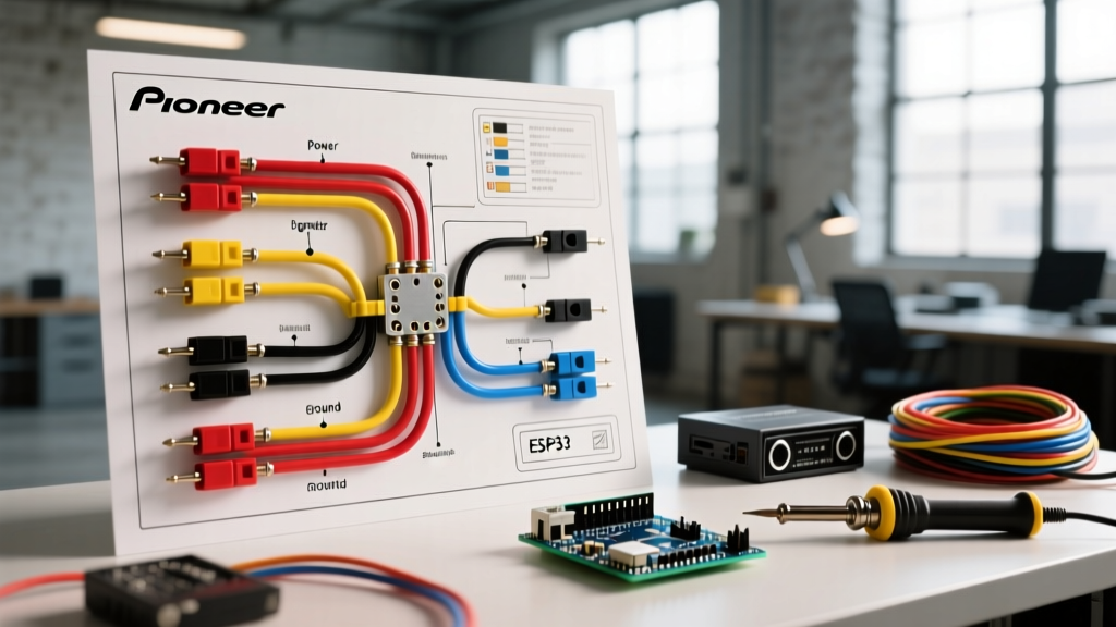
Anatomy of the Standard Pioneer 16-Pin Harness
Pioneer utilizes the standard EIA (Electronic Industries Alliance) color-coding scheme for its primary 16-pin power and speaker harness. While the wiring diagram included in your Pioneer box will show the exact pin layout, memorizing the core power and ground functions is essential for bench-testing and troubleshooting.
| Wire Color | Function | Recommended Gauge | Installation Notes |
|---|---|---|---|
| Yellow | 12V Constant (Memory) | 16 AWG | Connects directly to battery or constant 12V source. Maintains presets and clock. |
| Red | 12V Switched (Accessory) | 16 AWG | Turns the unit on/off with the ignition. Must read 0V when key is removed. |
| Black | Chassis Ground | 16 AWG | Must connect to bare, unpainted metal. Do NOT share a ground with high-draw amplifiers. |
| Blue/White | Amp Turn-On (Remote) | 18 AWG | Outputs +12V when the unit is on. Capable of triggering multiple relays. |
| Orange/White | Illumination / Dimmer | 18 AWG | WARNING: In CAN-bus vehicles, connecting this directly can trigger BCM faults. |
Note: While Pioneer ships most head units with 18 AWG wiring on the harness, high-power models (like those featuring built-in Class D amplifiers outputting 100W x 4) should have the Yellow, Red, and Black wires upgraded to 16 AWG during the adapter prep phase to prevent voltage drop and thermal throttling.
Decoding the Schematic: What the Dotted Lines Mean
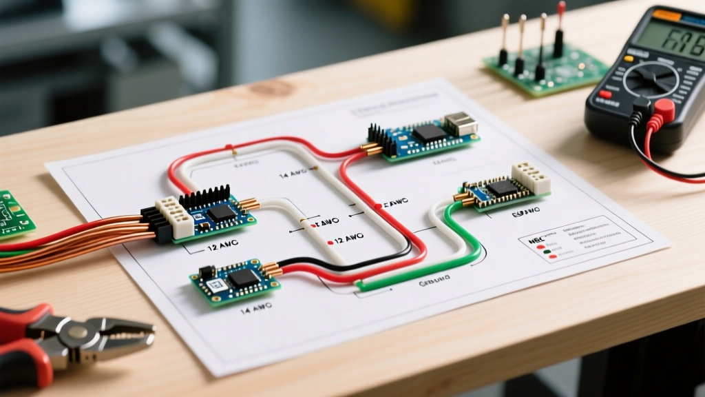
When you unfold the wiring diagram for a Pioneer car stereo from the manual, you will notice solid lines and dotted lines. Solid lines represent mandatory connections for basic operation. Dotted lines indicate optional features, vehicle-specific integrations, or external module connections.
Pro-Tip for CAN-Bus Vehicles (2018-2026 Models): If your wiring diagram shows the Orange/White illumination wire connecting to the vehicle's headlight circuit, pause. In modern multiplexed networks, tapping into the OEM illumination wire can backfeed voltage into the CAN-bus, causing dashboard warning lights. Instead, use a dedicated data interface module (like the PAC RP4-CH11 or Axxess XSVI-2104-NAV) that translates the CAN-bus wake-up signal into a safe 12V trigger for your Pioneer's Red accessory wire.
Pre-Install Bench Testing: The Professional's Secret
Never install a Pioneer head unit into a dashboard without bench-testing it first. Planning your install means verifying the wiring diagram's accuracy against your specific adapter harness before you are lying upside down under a steering column.
- Prepare a 12V Power Supply: Use a benchtop power supply or a spare 12V AGM battery. Connect the Pioneer Yellow wire to +12V, the Black wire to Ground, and the Red wire to a switched +12V terminal.
- Verify the Remote Turn-On: Use a digital multimeter (DMM) to probe the Blue/White wire. When you power on the Pioneer unit, the DMM should instantly read +12V. If it reads 0V, you have a defective head unit or a miswired harness.
- Test Speaker Phasing: Connect a single test speaker to the White (Front Left +) and White/Black (Front Left -) wires. Play a mono test tone. If the audio sounds 'hollow' or lacks bass when you cross the wires, you have identified a phase issue in your aftermarket adapter harness before it goes into the dash.
OEM Integration vs. Aftermarket Harness Adapters
A critical part of planning your installation is selecting the correct wiring interface. Cutting your vehicle's factory harness is strictly forbidden in modern automotive electronics; it voids warranties and destroys resale value. According to installation standards outlined by experts at Crutchfield's Learning Center, utilizing a vehicle-specific T-harness or hardwired adapter is mandatory.
Top Adapter Categories for Pioneer Integration
- Basic Power & Speaker (Non-Amplified): Metra 70-1761 (GM) or Metra 70-5511 (Ford). These simply translate the Pioneer 16-pin layout to the OEM plug.
- Steering Wheel Control (SWC): Axxess ASWC-1. This requires splicing into the Pioneer's specific SWC wires (usually found on a separate 3.5mm jack or a dedicated 8-pin harness) and the vehicle's data bus.
- Amplified Factory Systems (JBL, Bose, Harman Kardon): You will need an active line output converter (LOC) integrated into the wiring plan, as the Pioneer's low-level RCA outputs cannot bypass a factory amplifier without a bypass harness.
Connection Methods: Engineering for Longevity
The harsh environment of a vehicle dashboard—subject to extreme temperature cycling from -20°F to 160°F and constant vibration—will expose poor wiring connections. When mapping out your wiring diagram for a Pioneer car stereo, you must also plan your physical termination method.
| Connection Method | Vibration Resistance | Moisture Resistance | Verdict |
|---|---|---|---|
| Solder + Adhesive Heat Shrink | Excellent | Excellent | The gold standard. Mandatory for SWC and data wires. |
| Posi-Twist Connectors | Very Good | Good | Excellent for tight spaces where soldering is difficult. |
| Crimp Caps (Gel-filled) | Good | Excellent | Fast, but bulky. Can interfere with dash reassembly. |
| Electrical Tape Only | Poor | Poor | NEVER USE. Adhesive melts in summer heat, causing shorts. |
Common Edge Cases & Troubleshooting
Even with a perfect wiring diagram, real-world installations present unique electrical anomalies. Here is how to plan for the most common edge cases.
The 'Blue' vs 'Blue/White' Turn-On Trap
Pioneer head units often feature two blue wires: a solid Blue wire (Power Antenna) and a Blue/White wire (Amplifier Remote Turn-On). The solid Blue wire drops to 0V when you switch the source to CD or Bluetooth (because the radio tuner is off). If you wire your aftermarket amplifier to the solid Blue wire, your bass will cut out every time you play music from your phone via CarPlay or Android Auto. Always plan your amplifier remote wire to connect exclusively to the Blue/White stripe wire.
Alternator Whine and Ground Loops
If your planning phase skips a dedicated ground verification, you risk alternator whine—a high-pitched noise that revs with the engine. This occurs when the Pioneer head unit and the aftermarket amplifier are grounded at different chassis points with varying resistance, creating a ground loop.
The Fix: During the planning stage, use a DMM to measure resistance between your planned head unit ground point and your planned amplifier ground point. It should read less than 0.1 ohms. If it reads higher, scrape away paint and clear coat down to bare steel, or run a dedicated 10 AWG ground wire from the head unit chassis directly to the amplifier's main ground distribution block. For more on vehicle grounding standards, refer to the Metra Electronics technical resources.
Finalizing Your Install Plan
A successful car audio upgrade is 80% planning and 20% execution. By thoroughly studying the wiring diagram for a Pioneer car stereo, selecting the correct data-retention modules, and committing to marine-grade termination methods, you ensure your system will perform flawlessly for the life of the vehicle. Always double-check your specific vehicle's service manual for airbag (SRS) wire routing—typically identified by yellow looms—ensuring your new stereo harness never crosses or interferes with critical safety systems. For official schematics and firmware updates, always consult the Pioneer Electronics Support Portal before finalizing your dash reassembly.