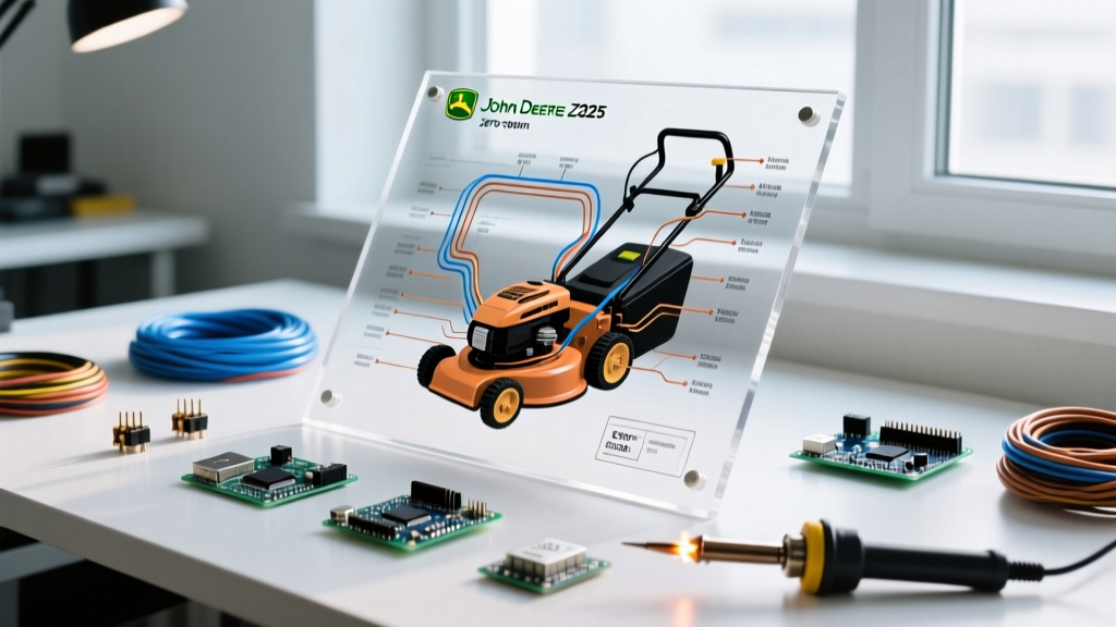

Why the John Deere Z425 Electrical System Fails
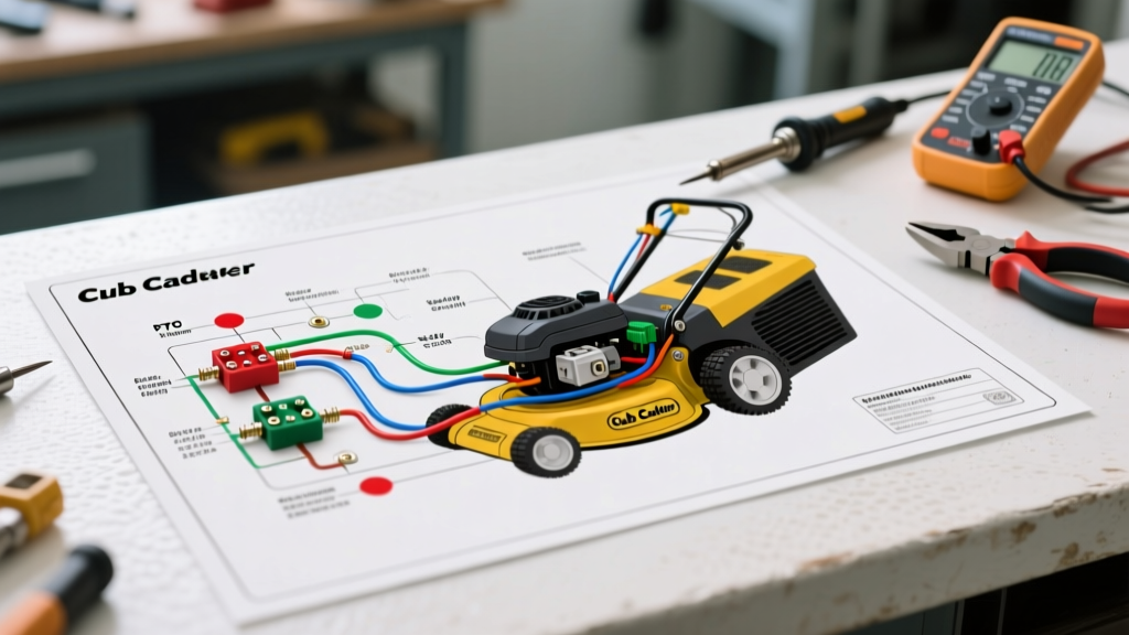
The John Deere Z425 zero-turn mower is a staple in both residential and light-commercial landscaping, typically powered by the robust 25HP Kawasaki FS651V engine. However, like all modern turf equipment, its reliability is tethered to a complex network of safety interlocks, relays, and high-draw electromagnetic clutches. When the mower refuses to start, the blades won't engage, or the engine mysteriously dies mid-mow, guessing is not an option. You need the wiring diagram for John Deere Z425 to isolate the fault.
Electrical failures on the Z425 rarely stem from the main harness itself; instead, they originate at connection points, failing safety switches, or degraded electromagnetic coils. According to the Outdoor Power Equipment Institute (OPEI), bypassing safety interlocks to diagnose a zero-turn mower is a leading cause of severe operator injury. Proper schematic reading allows you to diagnose the circuit safely without compromising the machine's engineered safety logic.
Decoding the John Deere Turf Wiring Legend
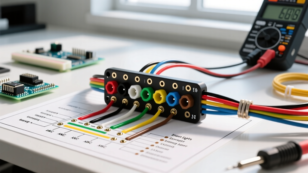
Before probing any wires with a multimeter, you must understand the standardized color codes and abbreviations used in John Deere turf schematics. While you should always verify against the specific legend on your Z425's schematic (usually found in the operator's manual or via John Deere Technical Publications), the following color codes are standard across most Z-series mowers of this era:
- RD (Red): Unswitched 12V+ battery power. Hot at all times.
- BK (Black): Chassis ground or battery negative return.
- WT (White): Safety interlock circuits (seat switches, brake pedals).
- PU (Purple): PTO clutch engagement and accessory power.
- YL (Yellow): Alternator/charging circuit from the Kawasaki engine stator.
- GN (Green): Lighting circuits and low-draw accessories.
Connectors on the diagram are labeled with a 'C' followed by a number (e.g., C10, C22). When troubleshooting, locate the physical connector on the harness and count the pins to match the schematic pinout. This is crucial for testing the Time Delay Module (TDM) or Safety Interlock relays.
Troubleshooting Scenario 1: PTO Clutch Refuses to Engage
The most common electrical complaint on the Z425 is a PTO (Power Take-Off) clutch that clicks but doesn't engage, or fails to respond entirely. The Z425 utilizes an electric PTO clutch (typically an Ogura or Warner unit) that requires a massive initial inrush current, followed by a steady holding current.
Step 1: Verify Coil Resistance
Disconnect the two-wire connector leading to the PTO clutch under the chassis. Set your digital multimeter (DMM) to Ohms (Ω). Measure the resistance across the clutch terminals. A healthy Z425 PTO clutch should read between 2.5 and 3.5 ohms at room temperature. If your meter reads 'OL' (Open Loop), the internal coil is burnt out and the clutch must be replaced. If it reads below 1.0 ohm, the coil has an internal short and will blow the PTO fuse immediately upon engagement.
Step 2: Check the Air Gap
Electrical diagrams only tell half the story. If the clutch coil tests good and receives 12V, but the blades still slip, the mechanical air gap is out of spec. Using a feeler gauge, measure the gap between the armature and the rotor. The specification is strictly 0.018 to 0.022 inches. If the gap exceeds 0.030 inches, the electromagnetic field cannot bridge the distance, resulting in a 'click' but no engagement. Adjust the three lock-nuts on the clutch face to restore the gap.
Step 3: Trace the Interlock Logic
If there is zero voltage at the PTO plug when the switch is pulled, consult the wiring diagram to trace the PTO relay circuit. The Z425 requires the operator to be in the seat (Seat Switch closed) and the brake pedal locked (Brake Switch closed) for the PTO relay to receive a ground path. A failed $15 seat switch will completely disable the 12V+ output to the purple PTO wire.
Troubleshooting Scenario 2: Starter Solenoid Clicks, No Crank
The Kawasaki FS651V engine relies on a 12V starter solenoid to bridge battery power to the starter motor. A single loud 'click' followed by silence usually indicates a voltage drop, not necessarily a dead starter. For deeper engine specifications, refer to the Kawasaki Engines official documentation.
Performing a Voltage Drop Test
Do not simply measure static battery voltage. A battery can show 12.6V at rest but drop to 7V under load if it has a bad cell or corroded terminals.
- Set your DMM to DC Volts.
- Place the red probe on the starter motor's main battery post (not the battery terminal itself, but the starter side of the cable).
- Place the black probe on a clean, unpainted metal surface on the engine block.
- Turn the ignition key to 'START'.
- The voltage reading must remain above 10.5V during the cranking attempt. If it drops to 8V or lower, you have high resistance in the positive cable, a failing battery, or poor engine grounding.
If the main post has 12V+ during cranking but the starter doesn't spin, the issue is internal to the starter motor (worn carbon brushes or a seized Bendix drive). If the solenoid doesn't click at all, use the wiring diagram to trace the ignition switch 'S' terminal wire (usually Yellow/Red) through the brake safety switch to the solenoid trigger post.
Troubleshooting Scenario 3: Engine Dies When Brake is Released
This is a classic safety interlock failure. The Z425 wiring diagram routes the seat switch, brake switch, and PTO switch through a logical sequence to ground the ignition coils, killing the engine if the operator leaves the seat while the PTO is engaged or the brake is off.
Testing the Seat Switch
The seat switch on the Z425 is typically a Normally Open (NO) switch that closes when the operator sits down. Locate the switch under the seat pan and disconnect the harness. With the DMM set to continuity, press the switch plunger down with your hand. The meter should beep (continuity). Release the plunger; the meter should read 'OL'. If the switch sticks or fails to make contact, the interlock module assumes the seat is empty and grounds the ignition kill wire (usually Black/Yellow) when you release the parking brake.
Z425 Multimeter Diagnostic Matrix
| Component | Test Type | Expected Reading (Pass) | Failure Mode / Action |
|---|---|---|---|
| Battery (Static) | DC Volts | 12.6V - 12.8V | Below 12.2V: Charge or load test battery. |
| Battery (Cranking) | DC Volts | Above 10.5V | Below 9.5V: Bad battery cell or cable corrosion. |
| PTO Clutch Coil | Ohms (Ω) | 2.5Ω - 3.5Ω | OL: Replace clutch. <1Ω: Internal short. |
| Stator (AC Output) | AC Volts | 28V - 35V AC (at 3600 RPM) | Below 20V AC: Replace Kawasaki stator. |
| Voltage Regulator | DC Volts | 13.8V - 14.4V (at battery) | Above 15V: Regulator failed, boiling battery. |
| Seat Switch | Continuity | Closed when pressed | Replace if stuck open or permanently closed. |
Known Wiring Harness Chafe Points on the Z425
When the wiring diagram indicates a circuit should be live, but you have no voltage at the component, suspect a broken wire inside the insulation. The Z425 has three notorious chafe points where the harness rubs against the chassis due to vibration and zero-turn articulation:
- The Steering Control Tower Pivot: Where the harness passes from the main chassis up into the steering lever assembly. Constant turning flexes the harness, eventually snapping the internal copper strands of the safety interlock wires.
- The Engine Control Panel Bracket: Near the throttle cable routing, the harness can rub against the sharp edge of the steel mounting bracket. Inspect this area for melted loom and exposed copper.
- The PTO Clutch Routing: The wire leading to the PTO clutch is exposed to extreme heat, debris, and moisture. Ensure the grommet passing through the frame rail is intact; water intrusion here causes rapid green corrosion and high-resistance failures.
Safety Warning: Always disconnect the negative battery terminal before probing resistance or continuity on the Z425 wiring harness. Testing continuity on a live circuit will instantly blow your multimeter's internal fuse and can cause a short circuit across the Kawasaki FS651V's sensitive voltage regulator.
Conclusion
Troubleshooting the electrical system of a John Deere Z425 doesn't require replacing parts on a whim. By systematically following the wiring diagram for John Deere Z425, verifying wire color codes, and using a multimeter to measure exact voltage drops and resistance values, you can pinpoint the exact point of failure. Whether it is a 3-cent corroded pin in a C-connector, a $15 seat switch, or a $150 PTO clutch, the schematic provides the definitive roadmap to get your zero-turn mower back in the field safely and efficiently.