
The Anatomy of a Remote Start Wiring Diagram
Installing an aftermarket remote starter is one of the most complex electrical modifications you can perform on a vehicle. Unlike simple accessory installations, a remote start system must seamlessly interface with the vehicle's immobilizer, CAN-bus network, and high-current ignition circuits. When interpreting a wiring diagram for remote start systems, the two most critical variables are wire color coding and American Wire Gauge (AWG) selection. Misinterpreting either will result in blown fuses, damaged vehicle ECUs, or a system that clicks but fails to crank the engine.
Safety & Compliance Note: Always adhere to MECP (Mobile Electronics Certification Program) standards for automotive electrical work. Never use household solid-core wire (like Romex) in a vehicle; automotive environments require stranded, multi-conductor wire rated for extreme temperature fluctuations and vibration.
Standard Color Codes Across Major Brands
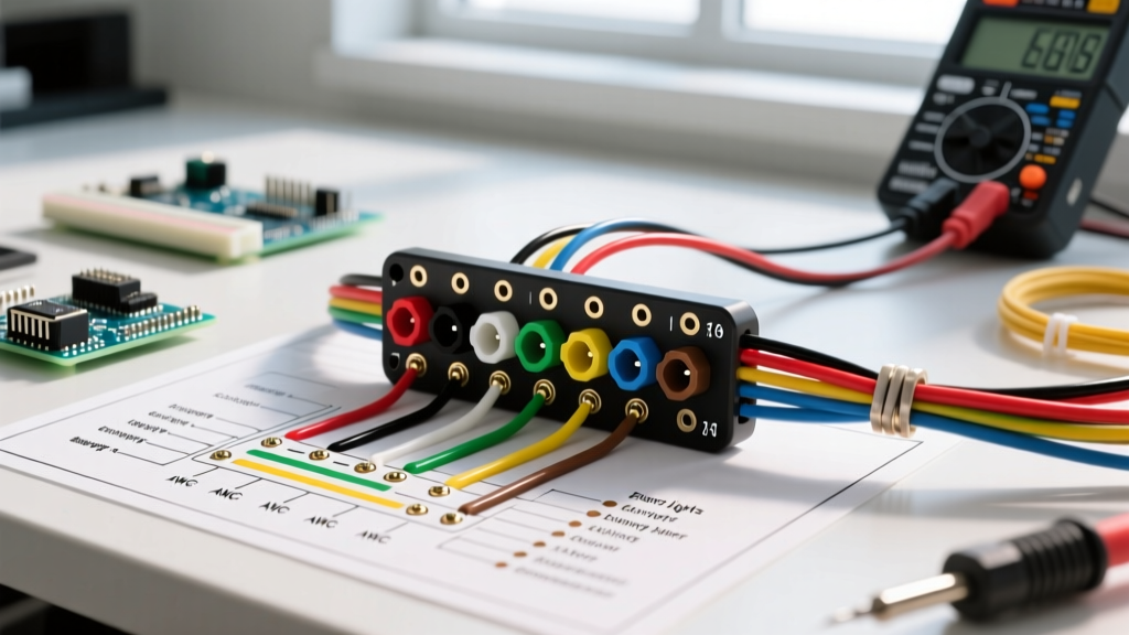
One of the biggest hurdles for DIYers and junior technicians is the lack of a universal color standard across manufacturers. While the vehicle's OEM harness follows specific SAE guidelines, the remote start brain (the module) uses proprietary color schemes. Below is a comparison matrix of the heavy-current ignition harness colors for the three dominant brands in the 2026 market.
| Circuit Function | Viper / DEI (6-Pin Harness) | Compustar (12-Pin Harness) | Fortin / EVO Series |
|---|---|---|---|
| 12V Constant Power | Red (+) | Red (+) | Red (+) |
| Starter Output | Purple | Yellow | Yellow |
| Ignition 1 (Primary) | Yellow | White | White |
| Ignition 2 (Secondary) | Pink | White/Red | Orange |
| Accessory | Orange | Green | Green |
| Ground | Black | Black | Black |
Pro Tip: Always verify the diagram included in your specific kit. Manufacturers occasionally update harness pinouts between hardware revisions (e.g., Compustar CM7000 vs. CM9000).
Wire Gauge Selection: SAE Standards & Circuit Loads
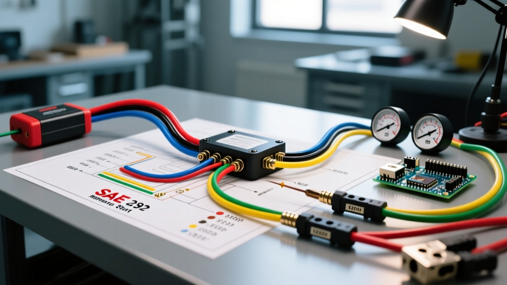
The wiring diagram for remote start modules will often indicate the required fuse size, but it rarely specifies the exact AWG you must use for your extension wires. According to SAE International (SAE J1128), automotive wire must handle specific thermal and electrical loads. For remote starts, you should exclusively use TXL (Cross-linked) or GXL wire rather than standard GPT. TXL wire features a thinner insulation wall, allowing for tighter routing in cramped dashboard cavities while maintaining superior heat resistance up to 125°C.
AWG Sizing Matrix by Circuit
| Circuit Type | Recommended AWG | Max Continuous Current | Required Fuse |
|---|---|---|---|
| Main 12V+ Power Feed | 10 AWG or 12 AWG | 40A - 50A | 40A MAXI |
| Main Chassis Ground | 10 AWG or 12 AWG | 40A - 50A | N/A (Bolted) |
| Starter Relay Output | 12 AWG or 14 AWG | 30A | 30A |
| Ignition 1 & 2 Outputs | 14 AWG or 16 AWG | 20A | 20A |
| Accessory Output | 14 AWG or 16 AWG | 15A | 15A |
| CAN-Bus / Data Lines | 18 AWG to 22 AWG | < 2A | N/A |
Step-by-Step: Hardwiring vs. T-Harness Integration
In modern vehicle architecture, the method of connection drastically alters how you read the wiring diagram.
- T-Harness (Plug-and-Play): For vehicles equipped with OBD2 or standardized ignition plugs, a T-harness intercepts the signals. Here, your wiring diagram primarily focuses on the CAN-bus data lines (typically 18-22 AWG) and a single 12V power/ground feed. The high-current switching is handled internally by the vehicle's OEM relays.
- Hardwiring (Universal): Required for older vehicles or complex European architectures. You must cut the OEM ignition switch wires and splice the remote start outputs in parallel. This requires strict adherence to the AWG matrix above, as the remote start module's internal relays are now carrying the full amperage load of the vehicle's ignition coils and fuel pumps.
Critical Edge Case: The Voltage Drop Failure
A common failure mode occurs when an installer uses 16 AWG wire to extend the Purple Starter Output on a Viper system. The starter solenoid on a modern V8 engine can draw 25 to 35 amps momentarily. If 16 AWG wire is used over a 4-foot run from the module to the vehicle harness, the resistance causes a severe voltage drop. The multimeter might read 12V at the module, but only 8.5V reaches the solenoid. The result? A loud 'click' from the relay, but the starter motor never engages. Always use a minimum of 12 AWG for starter circuits to mitigate voltage drop.
Pro-Grade Tools for 2026 Installations
To execute the wiring diagram for remote start systems flawlessly, you need precision tools. Electrical tape is obsolete for primary connections; modern standards demand heat-shrink butt connectors and proper crimping.
- Wire Strippers: Knipex MultiStrip 10 (Handles 10-24 AWG without nicking copper strands).
- Crimpers: Glarks SN-28B for standard insulated terminals, or a dedicated heat-shrink crimper like the Titan 11140.
- Digital Multimeter: Fluke 115 or 87V. You need a meter with a low-impedance (LoZ) mode to prevent ghost voltage readings on modern multiplexed CAN-bus networks.
- Soldering Iron (Optional but recommended): Weller WE1010NA for tinning stranded wire before inserting it into screw-terminals on heavy-duty relay packs.
Frequently Asked Questions
Do I need to connect both Ignition 1 and Ignition 2?
Yes, if your vehicle's OEM ignition switch powers two separate 12V+ feeds during the 'Run' and 'Start' positions. Consult a vehicle-specific wiring guide from Fortin's technical database or Mitchell1 to verify your vehicle's ignition topology. Bypassing Ignition 2 will often result in the engine cranking but immediately dying because the fuel pump or ECU is starved of power.
Can I ground the remote start module to the emergency brake bracket?
No. While the e-brake bracket is metal, it is often painted or powder-coated, creating a high-resistance path. The main ground wire (10-12 AWG) must be terminated to a bare, unpainted metal surface directly bolted to the chassis or engine block. Use a wire brush to clear away corrosion and paint before securing the ring terminal.
Why does the diagram show a diode on the tachometer wire?
Diodes (typically 1N4004) are used to isolate voltage. If your remote start diagram requires a diode on the tach signal or brake input, it is to prevent 12V+ backfeed from the remote start module into the vehicle's delicate OEM computer networks, which could fry the BCM (Body Control Module).