
Decoding the Schematic: Line vs. Control Voltage
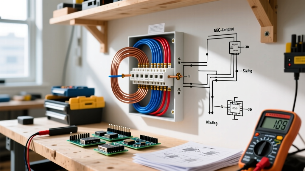
When a heat pump or electric furnace fails to produce auxiliary heat, the electric heat strip wiring diagram is your most critical diagnostic tool. Unlike gas furnaces that rely on complex ignition sequences, electric heat strips operate on a brutal but simple principle: passing high-amperage 240V line voltage through high-resistance Nichrome wire elements. However, the control side of the circuit is where 90% of diagnostic errors occur. Modern air handlers, such as the Goodman ASPT series or Rheem RHLL models, divide their schematics into two distinct zones: the 240V/208V line voltage circuit and the 24V control circuit.
According to the U.S. Department of Energy, electric resistance heat is nearly 100% efficient at converting electricity to heat, but because it draws massive current, improper wiring or degraded components can lead to catastrophic failures, including melted terminal blocks and electrical fires. Understanding how to trace the schematic from the thermostat's W terminal to the sequencer coils is the hallmark of a proficient HVAC technician.
The 240V Line Voltage Circuit
Line voltage enters the air handler through a dual-pole breaker, typically ranging from 30A to 60A depending on the kilowatt (kW) capacity. The wiring diagram will show L1 and L2 routing through manual-reset thermal limit switches, then into the heavy-duty contacts of the sequencers or contactors. When these contacts close, 240V is delivered directly to the heating elements.
The 24V Control Circuit
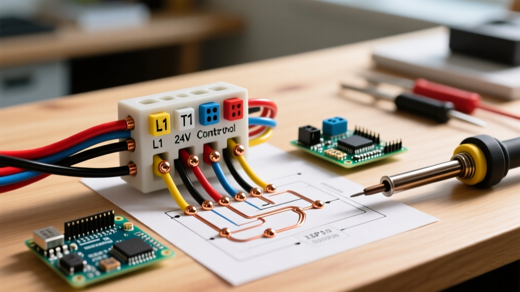
The control circuit originates at the air handler's control board or a dedicated 24V transformer. When the thermostat calls for auxiliary or emergency heat, it sends 24V AC from the W terminal to the sequencer coils. The wiring diagram maps this low-voltage path through a series of safety switches (like the high-limit and fusible links) before reaching the magnetic coils of the sequencers.
⚠️ CRITICAL SAFETY WARNING: Always perform Lockout/Tagout (LOTO) procedures before opening an air handler panel. Electric heat strips operate at lethal voltages and amperages. Adhering to NFPA 70E electrical safety standards is mandatory when testing live circuits with a multimeter.Step-by-Step Troubleshooting Using the Diagram
Use your schematic to isolate the fault. Do not guess; trace the voltage. Below are the two most common field scenarios and how to resolve them using the wiring diagram.
Scenario 1: Blower Operates, But No Auxiliary Heat
The indoor blower is pushing air, but the air is cold. The thermostat is calling for heat (W terminal energized).
- Verify Line Voltage: Set your multimeter to AC Voltage. Measure across L1 and L2 at the main lug block. You should read between 235V and 245V. If you read 0V, check the main service panel breaker. If you read 120V, you have a lost leg (one breaker pole has tripped or a feeder wire is broken).
- Check the 24V Signal: Measure across the W and C terminals at the control board or terminal strip. You must read 24V AC. If absent, the issue is upstream at the thermostat or control board.
- Trace the Safety Limits: Follow the 24V wire on the diagram from the W terminal through the thermal limit switches. Measure voltage across each limit switch. If you read 24V across a switch, it is open (tripped). Identify if it is an auto-reset or manual-reset limit. If a manual-reset limit has tripped, investigate the root cause (e.g., restricted airflow, dirty blower wheel) before resetting.
- Test the Sequencer Coil: If 24V reaches the sequencer coil but the contacts do not close, disconnect power and test the coil's resistance. A healthy sequencer coil (like a Honeywell BR240X11) typically reads between 20 and 50 ohms. An infinite reading (OL) indicates a burnt-out coil requiring sequencer replacement.
Scenario 2: Heat Strips Remain Engaged (Runaway Heat)
This is a severe hazard. The blower may be off, but the elements are glowing red, risking a structural fire. This occurs when the high-amperage 240V contacts inside the sequencer or contactor weld themselves together due to arcing.
- Immediate Action: Throw the main disconnect switch or trip the dual-pole breaker at the main panel immediately.
- Verify Welded Contacts: With power locked out, set your multimeter to Continuity or Ohms. Place probes across the line-side and load-side terminals of the sequencer. If you read near 0 ohms (continuity) while the 24V control circuit is de-energized, the contacts are welded shut.
- Resolution: Replace the faulty sequencer or contactor. Inspect the wiring diagram to ensure the replacement part matches the exact ampacity and pole configuration specified by the manufacturer.
Wire Gauge, Breaker Sizing, and kW Matrix
One of the most frequent code violations found during inspections is undersized wiring for the installed kW capacity. The electric heat strip wiring diagram will always specify the Minimum Circuit Ampacity (MCA) and Maximum Overcurrent Protection (MOP). Refer to the matrix below, derived from NEC Article 424, for standard residential applications at 240V:
| Heater Capacity (kW) | Approx. Amperage (240V) | Minimum Copper Wire Gauge (THHN/THWN) | Standard Dual-Pole Breaker |
|---|---|---|---|
| 5 kW | 21 Amps | 10 AWG | 30A |
| 10 kW | 42 Amps | 6 AWG | 50A |
| 15 kW | 63 Amps | 4 AWG | 70A |
| 20 kW | 84 Amps | 3 AWG (or dual 10kW circuits) | 90A (or dual 50A) |
Real-World Failure Modes in Modern Air Handlers
When consulting the wiring diagram, experienced technicians look for known weak points specific to modern manufacturing techniques. Here are two edge cases that rarely appear in basic manuals but dominate field service calls:
The 'Molex Melt' on 24V Harnesses
In many 15kW and 20kW air handlers, the 24V control wiring connects to the sequencers via plastic Molex-style plug connectors. Because a 20kW system may use three or four sequencers, the cumulative inrush current and holding current passing through the small pins of the Molex connector can generate significant heat. Over 5 to 7 years, this heat degrades the plastic housing, causing the pins to arc and melt. Diagnostic Tip: If your wiring diagram shows a multi-pin plug between the control board and the sequencer harness, physically disconnect it and inspect for brown scorch marks. If present, cut the plug out and splice the wires using high-temperature ceramic wire nuts or inline crimp connectors.
Thermal Grease Degradation on Limit Switches
Thermal limit switches are mounted directly to the heat strip assembly to monitor the chassis temperature. Manufacturers apply a dab of thermal conductive grease between the bimetal switch and the metal housing to ensure rapid heat transfer. If a previous technician replaced a limit switch and failed to apply fresh thermal paste (like Artic Silver or generic silicone thermal compound), the switch will react too slowly to a thermal runaway event, potentially allowing the auxiliary heat exchanger to warp before the circuit opens.
Expert Insight: When testing a 5kW heating element for continuity, expect a resistance reading of approximately 11.5 ohms (calculated via Ohm's Law: R = V² / P, so 240² / 5000 = 11.52Ω). If you read 0 ohms, the element is shorted. If you read infinite (OL), the Nichrome wire has snapped, often due to vibration fatigue or a localized hot-spot caused by restricted airflow.
Frequently Asked Questions (FAQ)
Can I wire a 10kW heat strip to a 30A breaker?
No. A 10kW strip at 240V draws roughly 41.6 Amps. Wiring it to a 30A breaker will cause nuisance tripping within minutes of operation and violates NEC overcurrent protection rules. You must use a 50A breaker and 6 AWG copper wire.
Why does my wiring diagram show two separate 24V transformers?
High-capacity systems (15kW+) often use a dedicated 40VA or 75VA transformer solely to power the sequencer coils and blower relay. The control board's internal transformer is reserved for low-draw logic circuits and the smart thermostat. Combining them on one transformer can cause a voltage drop below 18V AC, leading to chattering contactors and burnt-out coils.
Do I need to connect the E (Emergency) terminal if I have a smart thermostat?
Yes, if your system utilizes a dual-fuel setup or requires emergency heat bypass. The wiring diagram will show the E terminal bypassing the heat pump's defrost board and outdoor unit lockout, energizing the heat strips directly. Consult the EPA ENERGY STAR HVAC guidelines for optimal smart thermostat configuration to minimize expensive resistance heating usage.