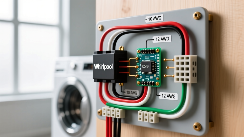

Understanding the Whirlpool Electric Dryer Heating Circuit
When a Whirlpool electric dryer—whether it is a Duet, Cabrio, or a Kenmore Elite rebrand—fails to produce heat, the heating element is the most common culprit. However, simply swapping the part without understanding the underlying electrical architecture is a recipe for repeated failures or, worse, a fire hazard. Interpreting the electric dryer wiring diagram for whirlpool dryer heating element circuits requires a firm grasp of wire gauge limitations, high-temperature insulation requirements, and precise color code routing.
Electric dryers operate on a 240-volt, 30-amp split-phase circuit. The heating element alone draws between 18 and 22 amps continuously during the high-heat cycle. According to the National Electrical Code (NFPA 70), any continuous load requires conductors rated for 125% of the load, meaning the internal wiring feeding the element must be robust enough to handle severe thermal stress without degrading.
Safety Warning: Always disconnect the dryer from the 240V power source at the main breaker panel before opening the rear access panel. The terminal block carries lethal voltage even when the dryer controls are in the 'Off' position. Verify zero voltage with a CAT III or CAT IV multimeter before touching any internal spade connectors.
Wire Gauge Specifications for Internal Heating Elements
The most critical mistake DIYers make when repairing a burnt heating element pigtail is using standard PVC-insulated THHN wire or undersized gauges. The internal environment of a Whirlpool dryer drum housing routinely exceeds 150°F (65°C), and localized heat near the element terminals can spike much higher. Standard wire insulation will melt, short against the metal chassis, and trip the main breaker—or ignite lint.
Internal Wiring Gauge & Insulation Matrix
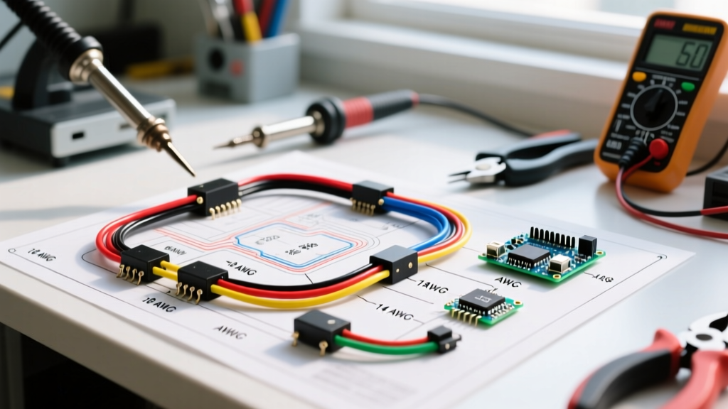
| Wire Gauge (AWG) | Max Ampacity | Required Insulation | Application in Whirlpool Dryer |
|---|---|---|---|
| 10 AWG | 30 Amps | Teflon (PTFE) / Fiberglass (200°C+) | Main terminal block to element pigtails; external power cord |
| 12 AWG | 20 Amps | High-Temp Fiberglass (200°C) | Heating element coil jumpers; high-limit thermostat feeds |
| 14 AWG | 15 Amps | Standard PVC / High-Temp | Motor circuits; timer logic; 120V neutral return paths |
| 18 AWG | 5 Amps | Standard PVC | Low-voltage sensor wires; moisture sensor strips |
When replacing a melted wire harness on a standard Whirlpool 279838 heating element, you must use a minimum of 12 AWG high-temperature Teflon or fiberglass-coated wire. These specialized appliance repair wires typically cost between $15 and $25 for a pre-crimped kit, which is a necessary investment compared to the $25-$45 cost of the heating element itself.
Internal Color Code Reference
Whirlpool utilizes a standardized color-coding system across its electric dryer lineup to differentiate between the 240V heating circuits and the 120V motor/timer circuits. Misrouting these wires will instantly destroy the timer board or blow the thermal fuse.
- Red & Black (Main Power): These are the two 120V hot legs (L1 and L2) arriving from the terminal block. They provide the 240V potential required by the heating element. Red typically routes through the high-limit thermostat, while Black routes through the thermal cutoff and cycling thermostat before reaching the element.
- White (Neutral): The 120V return path. This wire powers the drive motor, timer, and control board. It should never be connected to the heating element terminals.
- Green or Bare Copper (Ground): Bonds the metal chassis to the earth ground. In 4-prong setups, this is separate from the neutral. In older 3-prong setups, the neutral and ground are bonded at the terminal block via a copper strap.
- Blue, Orange, or Yellow (Switch Legs): These colors are used for internal switch drops, such as the wire running from the centrifugal switch on the drive motor to the heating element relay. This ensures the heater only engages when the drum is actively spinning.
Step-by-Step Diagnostic & Replacement Protocol
Before ordering a replacement heating element (common part numbers include 279838, 8544771, or 4391960 for the thermal cutoff kit), you must verify the failure point using a digital multimeter. The experts at Repair Clinic emphasize that a blown thermal fuse is often a symptom of restricted airflow, not just a random component failure.
- Access the Element: Remove the lower front access panel (on Duet models) or the entire rear panel (on traditional Cabrio models) to expose the heater housing.
- Test the Heating Element: Disconnect the two main wires from the element terminals. Set your multimeter to Ohms (Ω). Place the probes on the two element terminals. A healthy Whirlpool 279838 element will read between 10 and 15 ohms. A reading of 'OL' (Open Line) means the internal coil is broken and the element must be replaced.
- Test for Ground Fault: Keep one probe on a terminal and touch the other to the bare metal housing of the element box. The reading must be 'OL'. If it reads continuity (0 ohms), the element is shorting to the chassis and is a severe shock hazard.
- Verify the Thermal Cutoff & High-Limit: Test the thermal fuse (typically part #279816) and the high-limit thermostat (part #3977393). Both should read 0 ohms (continuity). If the thermal fuse is open, you must replace both the fuse and the cycling thermostat, as Whirlpool mandates they be replaced as a matched set to prevent future thermal runaway.
- Install with Proper Torque: When reconnecting the spade terminals to the new element, use needle-nose pliers to squeeze the female spade connectors tight. Loose connections create high electrical resistance, which generates localized heat and will melt the new wire harness within weeks.
3-Prong vs. 4-Prong Receptacle Configurations
A frequent edge case when installing or moving a Whirlpool dryer involves the transition between older 3-prong (NEMA 10-30) and modern 4-prong (NEMA 14-30) outlets. The U.S. Consumer Product Safety Commission (CPSC) heavily advocates for the 4-prong configuration because it separates the equipment grounding conductor from the neutral conductor.
If you are wiring a new power cord to the dryer's terminal block, you must adjust the internal bonding strap. In a 4-prong setup, the bonding strap connecting the center neutral terminal to the chassis ground screw must be removed or folded back. In a 3-prong setup, the bonding strap must be intact. Failing to configure this correctly can result in the dryer chassis becoming energized with 120V if the neutral wire fails, posing a lethal electrocution risk.
Common Failure Modes and Edge Cases
1. Melted Terminal Block
If the main power cord terminal block shows signs of scorching or melted plastic, the issue is rarely the heating element itself. It is almost always caused by loose terminal screws vibrating out of torque over years of operation, or the use of aluminum wire pigtails without proper antioxidant paste. Replace the entire terminal block kit (approx. $12-$18) and torque the screws to 20 in-lbs.
2. Repeated Thermal Fuse Blowing
If your new heating element works, but the thermal fuse blows again within three loads, you have an airflow restriction. The heating element relies on the blower wheel to pull air across the coils. If the blower wheel is stripped on the motor shaft, or if the internal ducting is packed with lint, the heat cannot escape the element housing. The thermal cutoff will trip at 305°F to prevent a fire. Always inspect the blower wheel and vent hose before assuming an electrical fault.
3. Cycling Thermostat Failure
The cycling thermostat regulates the internal drum temperature by cycling the 240V power to the heating element on and off. If the contacts inside the thermostat weld themselves shut due to arcing, the element will stay on continuously until the high-limit thermostat or thermal cutoff acts as a failsafe. If you find a melted wire specifically on the cycling thermostat, replace the thermostat and upgrade the connecting wire to a 12 AWG high-temp fiberglass lead.