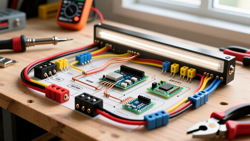

Why a Relay Harness is Non-Negotiable for Modern LED Light Bars
Installing a high-output LED light bar on a truck, SUV, or off-road rig requires more than simply splicing into your factory headlight circuit. Modern 50-inch dual-row LED light bars from premium manufacturers like Rigid Industries or Baja Designs can draw anywhere from 15 to 30 amps under peak load. If you attempt to route this current through a standard dashboard toggle switch or a factory headlight stalk, you risk melting the switch housing, causing a voltage drop that dims the LEDs, or worse, starting an electrical fire.
The solution is a dedicated 4-pin relay harness. This guide provides the definitive wiring diagram for light bar relay setups, breaking down exact wire gauges, fuse placement protocols, and step-by-step routing procedures based on SAE (Society of Automotive Engineers) standards. By isolating the high-amperage load from the low-amperage trigger switch, you ensure maximum luminosity, circuit longevity, and vehicle safety.
Anatomy of the 4-Pin Automotive Relay
At the heart of the wiring diagram for light bar installations is the standard ISO mini 4-pin relay (often referred to as a Bosch-style relay). Understanding the pinout is critical for proper harness assembly. According to Littelfuse Automotive Relays documentation, the standard pin configuration operates as follows:
- Pin 30 (Common / Power In): Connects directly to the vehicle battery positive terminal via an inline fuse. This is the high-amperage feed.
- Pin 87 (Normally Open / Power Out): Connects to the positive wire of the LED light bar. When the relay is energized, power flows from Pin 30 to Pin 87.
- Pin 86 (Coil Positive / Trigger In): Connects to the low-amperage dashboard switch, which receives power from an ignition-switched fuse.
- Pin 85 (Coil Negative / Ground): Connects to a clean, bare-metal chassis ground. This completes the electromagnetic coil circuit, pulling the internal switch closed.
Wire Gauge and Fuse Sizing Matrix
Selecting the correct wire gauge is dictated by the total amperage draw and the length of the wire run. Using Copper Clad Aluminum (CCA) wire or cheap PVC-jacketed wire is a common failure point; PVC insulation melts at lower temperatures and degrades quickly in engine bays. Always specify SAE J1128 GXL or TXL cross-linked polyethylene wire, which withstands engine bay temperatures up to 125°C (257°F). Reference the Blue Sea Systems Wire Sizing Guide for the matrix below, calculated for a standard 15-foot round-trip wire run with a 3% voltage drop threshold.
| Light Bar Wattage | Amperage Draw (at 13.8V) | Recommended SAE GXL Wire Gauge | Inline ATO/ATC Fuse Size |
|---|---|---|---|
| 120W (20-inch) | 8.7A | 14 AWG | 15A |
| 240W (30-inch) | 17.4A | 12 AWG | 20A |
| 360W (40-inch) | 26.1A | 10 AWG | 30A |
| 500W+ (50-inch Dual Row) | 36.2A+ | 8 AWG | 40A |
Step-by-Step Installation & Routing Protocol
Follow this sequence to execute the wiring diagram for light bar setups with professional-grade reliability.
- Establish the Main Power Feed: Crimp a 3/8-inch ring terminal to your main power wire (e.g., 10 AWG GXL). Secure it to the vehicle's battery positive terminal. Critical Rule: The inline ATO/ATC fuse holder must be installed within 18 inches of the battery terminal. This ensures the entire length of the wire is protected against short circuits.
- Route Through the Firewall: Never drill a new hole through the firewall unless absolutely necessary. Locate an existing factory rubber grommet (often near the brake booster or main ECU harness). Use a silicone-based wire lubricant and a blunt fish tape to pull the relay harness into the cabin without tearing the rubber seal, which would allow carbon monoxide and water into the cab.
- Mount the Relay: Secure the 4-pin relay in the engine bay using a zip-tie mount or bolted bracket. Keep it away from the exhaust manifold and moving belts. Mount the relay with the pins facing downward to prevent water from pooling inside the connector socket.
- Terminate the Ground (Pin 85): Locate a factory bolt on the chassis or engine block. Remove the bolt, use a wire brush or sandpaper to strip away paint and powder coating down to bare metal, and attach the ground ring terminal. Secure with a star washer to bite into the metal, and coat the finished connection in dielectric grease to prevent galvanic corrosion.
- Connect the Load (Pin 87): Route the output wire to the roof rack or bumper. Use 3M heat-shrink butt connectors (nylon-lined, not vinyl) to join the harness to the light bar's pigtail. The nylon lining melts and seals the crimp, making it 100% waterproof.
Triggering the Switch: Add-A-Circuit vs. Wire Piercing
To power the dashboard switch (which feeds Pin 86), you need an ignition-switched 12V source so the light bar automatically turns off when you remove the keys. Never use scotch locks or wire-piercing taps. These slice through the wire's insulation, exposing raw copper to moisture and causing green rot (copper oxidation) that will eventually break the factory circuit.
Instead, use an Add-A-Circuit (ATO fuse tap) in the vehicle's interior fuse box. Locate a fuse that is only active in the 'Run' or 'Accessory' position (such as the windshield wipers or 12V auxiliary outlet). Plug the Add-A-Circuit into this slot, insert a 3A fuse for your new switch circuit, and route the tap wire through the firewall to your dashboard toggle switch.
Diagnostic Guide: Common Failure Modes
Even with a perfect wiring diagram for light bar setups, environmental factors and installation errors can cause issues. Use this troubleshooting matrix to diagnose problems:
Symptom: Relay Clicks Rapidly (Chatter) but Lights Flicker
Diagnosis: Voltage drop on the trigger circuit. The electromagnetic coil inside the relay requires at least 10.5V to hold the switch closed. If you are using an excessively long run of thin 18 AWG wire for the dashboard switch trigger, the voltage drops below the threshold. Fix: Upgrade the trigger wire to 14 AWG or move the relay closer to the battery and switch.
Symptom: Light Bar Turns On, But Glows Dimly with a Yellow Tint
Diagnosis: Severe voltage drop on the main power or ground side. High-power LEDs shift color temperature when they do not receive adequate voltage. Fix: Use a digital multimeter to measure voltage directly at the light bar's connector while it is turned on. If it reads below 12.5V, your wire gauge is too thin for the distance, or your chassis ground is corroded.
Symptom: Light Bar Stays On After Turning Off the Ignition
Diagnosis: The Add-A-Circuit fuse tap was installed on a 'constant 12V' circuit (like the hazard lights or horn) instead of a switched circuit, or the relay is internally welded shut due to a massive short circuit that fused the contacts. Fix: Verify the fuse tap source with a multimeter (should read 0V with keys off). If the tap is correct, replace the relay immediately.
By adhering strictly to SAE wire standards, utilizing proper heat-shrink terminations, and respecting the 18-inch fuse rule, your light bar installation will withstand the harshest off-road vibrations and weather conditions for years to come.