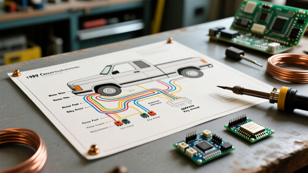

The 'Motor Wiring' Approach to Car Audio Installations
When engineers design high-torque motor controllers for EV conversions, marine vessels, or heavy machinery, they employ rigorous grounding and signal-isolation techniques to prevent back-EMF and PWM noise from corrupting sensitive logic boards. Surprisingly, most consumer car audio guides ignore these principles. If you are following a standard wiring diagram for stereo system setups in modern vehicles equipped with high-output alternators, electric power steering (EPS) motors, and start-stop technology, you are highly susceptible to alternator whine, ground loops, and EMI (Electromagnetic Interference).
At Electrical Flux, we apply industrial motor-wiring protocols to automotive audio. This guide provides a comprehensive, noise-free wiring diagram for stereo system architectures, ensuring your high-fidelity audio remains pristine regardless of the electrical chaos generated by the vehicle's drivetrain.
Core Wiring Diagram for Stereo System: Component Breakdown
A professional-grade stereo system relies on five distinct circuit paths. Treating these paths with the same respect as a 48V motor controller circuit is the key to a noise-free install.
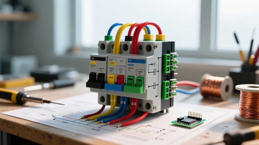
- Main Power Circuit (High Current DC): Runs from the battery positive terminal to the amplifier distribution block. Must be fused within 18 inches of the battery.
- Chassis Ground Circuit (High Current DC): Connects the amplifier ground to the vehicle chassis. This is where 90% of motor noise issues originate.
- Remote Turn-On Circuit (Low Current DC): A 12V+ trigger wire from the head unit to the amplifier's remote terminal.
- Signal Circuit (Low Voltage Analog/Digital): RCA cables or digital optical/coaxial cables carrying the audio signal. Must be shielded and routed away from power.
- Speaker Output Circuit (High Voltage AC): Amplified speaker wires running to the transducers.
Wire Gauge & Current Draw Matrix
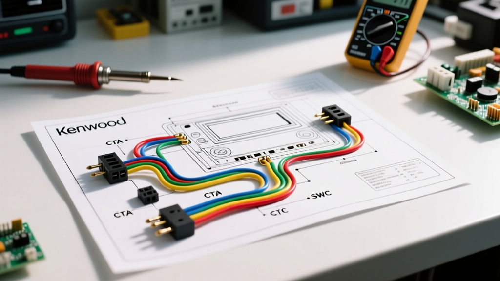
Using undersized wire causes voltage drop, forcing amplifiers to draw excess current, which generates heat and introduces clipping distortion. The Consumer Technology Association (CTA) mandates strict adherence to AWG sizing based on total RMS wattage and cable length. Note: The chart below assumes 100% Oxygen-Free Copper (OFC). If using Copper-Clad Aluminum (CCA), you must step up one gauge size (e.g., use 2 AWG instead of 4 AWG).
| Total System RMS Wattage | 0-10 ft Run | 10-20 ft Run | 20-30 ft Run | Main Fuse Rating |
|---|---|---|---|---|
| 0 - 400W | 8 AWG | 8 AWG | 4 AWG | 40A MAXI |
| 400W - 1000W | 4 AWG | 4 AWG | 2 AWG | 80A ANL |
| 1000W - 2000W | 2 AWG | 1/0 AWG | 1/0 AWG | 150A ANL |
| 2000W - 4000W+ | 1/0 AWG | 2/0 AWG | 4/0 AWG | 250A+ ANL |
Step-by-Step Routing & Grounding Protocol
To eliminate the ground potential differences that cause alternator whine (a high-pitched noise that rises and falls with engine RPM), we utilize a Star Grounding topology, a staple in industrial motor wiring.
- Power Wire Routing: Run the main power cable down the driver's side of the vehicle, utilizing existing factory grommets through the firewall. Never drill a new hole without using a rubber grommet and applying dielectric grease to prevent moisture ingress and chassis shorting.
- Signal Wire Routing: Run all RCA and speaker wires down the passenger side of the vehicle. Maintaining a minimum 12-inch separation between high-current DC power and low-voltage analog signals prevents magnetic field induction.
- Head Unit Grounding: Do not rely on the factory dash harness ground. Run a dedicated 12 AWG ground wire from the head unit's metal chassis directly to a clean, bare-metal point on the vehicle's steel subframe behind the dash.
- Amplifier Star Ground: Sand a 2-inch diameter circle on the vehicle's chassis in the trunk/cabin area down to bare, shiny metal. Use a stainless steel bolt, a heavy-duty copper ring terminal, and a star washer to bite into the metal. Torque to 12-15 ft-lbs. Coat the connection with conductive anti-oxidant grease to prevent rust, which increases resistance over time.
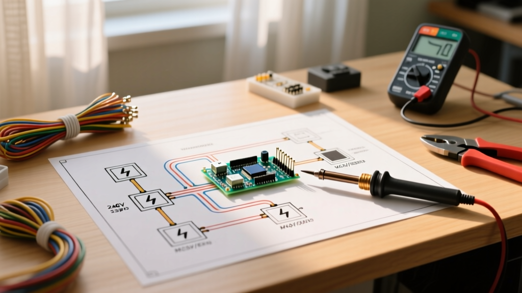
- Establishing Equipotential Grounding: If your head unit and amplifier are grounded at different physical locations, the vehicle's chassis resistance creates a millivolt differential. The alternator's AC ripple exploits this differential, injecting noise into the RCA shields. To fix this, run a 10 AWG 'ground loop prevention' wire directly from the head unit's dedicated ground point to the amplifier's star ground block, equalizing the potential.
Expert Insight: Never use a seatbelt bolt for your amplifier ground. Seatbelt bolts are often treated with high-strength Loctite and sit on isolated washers that prevent a true electrical bond to the chassis. Always use a dedicated, factory-verified grounding stud or drill into a structural crossmember. For more on proper automotive electrical bonding, refer to the JL Audio Technical Support archives.
Troubleshooting Motor Whine & EMI Failure Modes
Even with a perfect wiring diagram for stereo system layouts, modern vehicles with regenerative braking and high-amperage EPS motors can introduce anomalies. Use this diagnostic matrix to isolate the failure mode.
| Symptom | Probable Cause | Motor-Wiring Style Fix |
|---|---|---|
| Whine pitch changes with engine RPM | Ground loop / Alternator AC ripple | Verify star ground; add equipotential bond wire between HU and Amp ground. |
| Static 'popping' when EPS motor engages | EMI radiation from high-current steering motor | Reroute RCA cables away from steering column; use twisted-pair shielded RCAs. |
| Audio cuts out during heavy bass hits | Voltage drop / Headlight dimming | Upgrade alternator output; add a 2.0 Farad carbon capacitor or LiFePO4 auxiliary battery. |
| High-frequency hiss at idle | Fuel injector PWM noise coupling | Install a 12V DC power line filter (choke) on the head unit's constant 12V memory wire. |
2026 Component Recommendations for High-Noise Environments
When executing this wiring diagram for stereo system architectures in late-model vehicles, component selection matters as much as the wire routing. We recommend gear with high PSRR (Power Supply Rejection Ratio) and differential-balanced inputs.
Amplifiers with Differential-Balanced Inputs
Standard single-ended RCA inputs measure the signal against the chassis ground, making them vulnerable to noise. Differential-balanced inputs (found on the JL Audio VX800/8 and AudioControl DM-810) measure the voltage difference between the RCA center pin and the outer shield, actively rejecting any noise induced equally on both conductors. This is the audio equivalent of a motor controller's differential CAN-bus line.
Head Units with High-Voltage Preouts
The Pioneer DMH-WT8600NEX features 5-Volt RCA preouts. By pushing a 5V signal instead of the standard 2V, you drastically improve the signal-to-noise ratio (SNR). Any EMI induced by the vehicle's drivetrain becomes mathematically insignificant compared to the massive 5V audio signal, rendering ground loop isolators completely unnecessary.
Wiring Kits: OFC vs. CCA
Avoid bargain-bin wiring kits. In 2026, the market is flooded with CCA (Copper-Clad Aluminum) wire disguised as OFC. CCA has 40% higher electrical resistance and is brittle, leading to micro-fractures at crimp terminals that cause arcing. Always source 100% OFC kits from reputable brands like Knudsen or True Spec Wiring (available via Crutchfield). Look for the copper cross-section at the cut end; if it is silver or white in the center, it is CCA.
Final Inspection & Safety Protocols
Before connecting the main power wire to the battery, perform a multimeter continuity test. Set your multimeter to the continuity (beep) setting. Place one probe on the amplifier's ground terminal and the other on the vehicle's negative battery terminal. You should read near-zero ohms (under 0.5Ω). Next, check for shorts by placing one probe on the main power wire (disconnected from battery) and the other on the chassis. It should read 'OL' (Open Loop). If it reads continuity, you have a pinched wire that will cause a catastrophic short and potential vehicle fire the moment the fuse is seated.
By treating your car audio installation with the same rigorous, noise-mitigating principles used in industrial motor wiring, you guarantee a system that delivers studio-quality sound, completely isolated from the harsh electrical environment of the modern automobile.