
Introduction to Goodman Condenser Wiring
Wiring an outdoor air conditioner condenser requires a precise understanding of both high-voltage power delivery and low-voltage control circuits. Whether you are installing a standard single-stage GSX16 or a modern variable-speed GSZC20 heat pump, interpreting the wiring diagram for Goodman AC unit schematics is the most critical step in the process. As of 2026, Goodman (now operating under Daikin's manufacturing umbrella) utilizes highly standardized ladder diagrams and pictorial schematics, typically affixed to the inside of the condenser's main access panel.
This appliance wiring tutorial will break down the exact specifications, wire gauge requirements, and terminal mappings needed to safely wire a Goodman condenser, ensuring compliance with the National Electrical Code (NEC) Article 440 for Air-Conditioning and Refrigerating Equipment.
⚠️ HIGH VOLTAGE WARNING: Outdoor condensers operate on 208/240V AC. Lethal voltage is present at the disconnect and contactor. Always verify the circuit is dead using a Category III or IV multimeter before touching any terminals.Decoding the Wiring Diagram for Goodman AC Unit Schematics
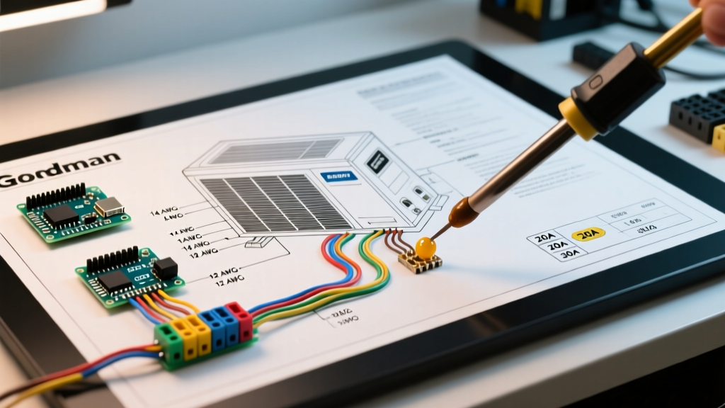
Goodman provides two types of diagrams on the access panel: the Pictorial Diagram (showing physical wire routing and colors) and the Ladder Diagram (showing the logical electrical flow). For troubleshooting and initial wiring, the ladder diagram is vastly superior.
Line Voltage vs. Low Voltage Control Circuits
The schematic is visually divided into two distinct sections:
- Line Voltage (208/240V): This circuit runs from your home's main electrical panel, through the exterior disconnect box, into the unit's contactor, and finally to the compressor and condenser fan motor.
- Low Voltage (24V): This circuit originates from the indoor air handler or furnace's control board, travels through the thermostat, and terminates at the condenser's contactor coil to actuate the system.
Essential Component Breakdown
Before making any connections, familiarize yourself with the standard schematic symbols and their physical counterparts inside the Goodman cabinet.
| Component | Schematic Symbol | Typical Specification (2026 Models) | Function |
|---|---|---|---|
| Contactor | K1 / C | 24V Coil, 30A or 40A Poles | Acts as a heavy-duty relay to send 240V to the compressor and fan. |
| Dual Run Capacitor | C / CAP | 45+5 µF, 440V AC | Provides the phase shift needed to start and run the compressor and fan motors. |
| Compressor Motor | COMP / M | R, S, C Terminals (Scroll or Reciprocating) | Pumps refrigerant through the system. Draws the highest amperage. |
| Condenser Fan Motor | FAN / M | 1/4 HP to 1/2 HP, 825-1050 RPM | Pulls ambient air across the condenser coil to reject heat. |
| High-Pressure Switch | HPS | Auto-reset, normally closed | Breaks the 24V control circuit if head pressure exceeds safe limits (approx. 610 PSI). |
Step-by-Step Appliance Wiring Tutorial: Line Voltage (240V)
The most common DIY and junior-technician error is misinterpreting the Minimum Circuit Ampacity (MCA) and Maximum Overcurrent Protection (MOCP) values listed on the Goodman data plate. According to EPA Energy Star guidelines and NEC standards, the breaker size must not exceed the MOCP, while the wire gauge must be sized to handle the MCA.
Sizing the Disconnect, Wire, and Breaker
Below is a reference matrix for standard Goodman GSX16 series condensers. Always verify against your specific unit's data plate.
- GSX160241 (2 Ton): MCA 14.2A | MOCP 25A | Use 12 AWG wire, 25A or 30A breaker.
- GSX160361 (3 Ton): MCA 21.4A | MOCP 35A | Use 10 AWG wire, 35A breaker.
- GSX160481 (4 Ton): MCA 28.1A | MOCP 45A | Use 8 AWG wire, 40A or 45A breaker.
- GSX160601 (5 Ton): MCA 34.8A | MOCP 50A | Use 8 AWG or 6 AWG wire, 50A breaker.
Routing the Whip and Terminating the Contactor
- Prepare the Whip: Use a 240V AC whip (liquid-tight flexible metal conduit with pre-installed THHN wires). Strip the outer jacket and route the wires through the condenser's liquid-tight connector.
- Grounding: Terminate the bare copper or green ground wire to the unit's designated grounding lug on the chassis. Never daisy-chain grounds.
- Line Side (L1 & L2): Connect the black and red (or black and white with black tape) hot wires to the top terminals of the contactor, labeled L1 and L2.
- Load Side (T1 & T2): Factory wiring connects the bottom terminals (T1 and T2) to the compressor contactor poles, the fan motor, and the capacitor. Verify these factory spade connections are tight; loose connections cause arcing and contactor pitting.
Routing the Low-Voltage Thermostat Wires
The low-voltage circuit controls the 24V coil inside the contactor. You will typically use 18/5 or 18/8 solid copper thermostat wire. For standard single-stage cooling, you only need three conductors: R (24V Power), C (24V Common), and Y (Compressor Call).
The Control Circuit Path
Trace the 24V path on your wiring diagram for Goodman AC unit schematics:
- The Y wire from the thermostat enters the condenser cabinet.
- It splices into the High-Pressure Switch (HPS) and, on newer models, the Low-Pressure Switch (LPS).
- After passing through the safety switches, the wire connects to one side of the contactor coil (often labeled A1 or simply a small spade terminal).
- The C wire from the thermostat connects directly to the other side of the contactor coil (A2).
Pro Tip: If your thermostat wire run exceeds 50 feet, voltage drop across the 18 AWG wire can cause the contactor to 'chatter' (rapidly engage and disengage). Upsize to 16 AWG thermostat wire for long runs to ensure a solid 24VAC pull at the coil.
Capacitor Wiring: Avoiding the Fatal Reversal
The dual run capacitor is the most frequently replaced component in a Goodman condenser. It has three terminals: C (Common), HERM (Hermetic/Compressor), and FAN.
When replacing a failed capacitor (e.g., upgrading to a heavy-duty 440V Titan Pro model), wiring the HERM and FAN terminals backward will result in the fan motor running backward or the compressor failing to start, eventually tripping the internal thermal overload.
- C (Common): Receives line voltage from the contactor T2 terminal. Shares a common winding with both motors.
- HERM: Connects exclusively to the compressor's 'Start' winding.
- FAN: Connects exclusively to the condenser fan motor's brown start wire.
Common Wiring Faults and Multimeter Troubleshooting
Even with a perfect understanding of the wiring diagram, field conditions introduce variables. Here is how to troubleshoot common electrical faults using a digital multimeter (DMM), adhering to NEMA motor testing standards.
Fault 1: Contactor Pulls In, but Compressor Hums and Trips
Diagnosis: The contactor is receiving 24V and closing the 240V circuit, but the compressor lacks the phase shift to start rotating.
Action: Set your DMM to measure capacitance (µF). Discharge the capacitor safely with a 20k-ohm resistor, then measure between C and HERM. If your schematic calls for a 45 µF capacitor and your reading is below 40 µF (a >10% drop), the capacitor is degraded and must be replaced.
Fault 2: Compressor Runs, but Fan Motor is Dead
Diagnosis: Power is reaching the unit, but the fan circuit is open.
Action: Check the 240V across the contactor's T1 and the FAN terminal on the capacitor. If 240V is present but the fan is dead, check the fan motor's internal thermal overload. Allow the motor to cool for 30 minutes. If it still fails to spin, the motor windings are open, and the motor requires replacement.
Fault 3: Thermostat Calls for Cool, but Contactor Does Not Engage
Diagnosis: The 24V control circuit is open.
Action: Measure AC voltage across the two small coil terminals on the contactor. If you read 0V, the issue is upstream. Check the high and low-pressure switches for continuity. If the refrigerant charge is low, the LPS will remain open, intentionally preventing the contactor from engaging to protect the compressor from liquid slugging.
Final Safety and Commissioning Checklist
Before re-energizing the system, perform this mandatory physical inspection:
- Verify all spade connectors are fully seated and crimped tightly. A loose connection on the capacitor will arc, melt the terminal, and cause a catastrophic failure.
- Ensure no loose wire clippings or stripped insulation pieces are resting on the contactor or compressor terminals.
- Confirm the disconnect box outside is rated for the MOCP and that the pull-out block or rotary switch is fully seated.
- Reinstall the Goodman access panel. The unit's safety interlock switches (if equipped on newer 2025/2026 models) will prevent the unit from operating if the panel is removed.
By meticulously following the wiring diagram for your specific Goodman AC unit and respecting the MCA/MOCP data plate specifications, you ensure a safe, efficient, and code-compliant installation that will maximize the lifespan of your HVAC investment.