
The Hidden Flaws in Factory 125cc ATV Wiring
If you own a TaoTao, Coolster, Roketa, or Kazuma 125cc quad, you are likely familiar with the 152FMI or 154FMI engine platforms. While these engines are remarkably durable, the electrical harnesses powering them are notoriously undersized. In 2026, the aftermarket support for these machines is better than ever, yet manufacturers continue to ship them with fragile inline glass fuses, copper-clad aluminum (CCA) wire, and non-existent centralized fuse panels. When you attempt to use the electric start, the starter motor can draw a peak stall current of 80 to 110 amps. Pushing this current through a factory 12 AWG inline fuse holder results in severe voltage drops, melted plastic housings, and eventual starter solenoid failure.
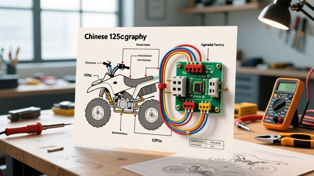
This guide approaches the electric start Chinese 125cc ATV wiring diagram from a Panel & Breaker perspective. We will decode the factory harness, identify the critical failure points in the power distribution, and provide a comprehensive blueprint for installing a marine-grade main circuit breaker and centralized fuse block.
Decoding the Electric Start Chinese 125cc ATV Wiring Diagram
Chinese ATV wiring diagrams are infamous for inconsistent color coding. A wire that is yellow on a 2024 TaoTao Boulder B1 might be pink on a 2025 Coolster 3125R. However, the functional topology of the electric start and power distribution circuits remains largely identical across the 110cc-125cc range.
Core Circuit Topology
- Main Power Feed (Typically Red): Runs from the battery positive terminal to the main inline fuse, then to the ignition switch and starter solenoid.
- Starter Engagement (Typically Black/Yellow or Blue): Routes from the start button relay to the starter solenoid trigger terminal.
- Stator Output (Yellow/White): Carries raw AC voltage from the stator to the regulator/rectifier.
- System Ground (Green or Black): Returns current to the battery negative and engine block.
Expert Warning: Never trust the factory wiring diagram printed in the owner's manual. Always trace the physical wires with a multimeter. Chinese factories frequently substitute wire colors based on whatever spool is available on the assembly line that day.
Panel & Breaker Guide: Designing a Reliable Power Distribution Hub
The factory setup relies on a single 30A blade or glass fuse suspended in an inline rubber holder near the battery. This is a massive bottleneck. To build a reliable system, we must replace this inline fuse with a centralized panel and a high-amperage thermal breaker.
| Component | Factory Spec (Typical) | Upgraded Panel Spec (2026 Standard) |
|---|---|---|
| Main Overcurrent Protection | 30A Glass/Blade Inline Fuse | 40A or 50A Marine Thermal Breaker |
| Main Feed Wire | 12 AWG CCA (Copper-Clad Aluminum) | 10 AWG Tinned OFC (Oxygen-Free Copper) |
| Accessory Distribution | Inline splices with electrical tape | 6-Circuit ST Blade Fuse Block |
| Voltage Drop @ 80A Crank | 0.8V - 1.5V (Causes solenoid chatter) | < 0.15V (Crisp solenoid engagement) |
| Estimated Upgrade Cost | $0 (Included with ATV) | $55 - $75 (Breaker + Block + Wire) |
Step-by-Step Main Circuit Breaker & Fuse Block Installation
Upgrading your power distribution requires precision. Follow these steps to install a robust breaker panel system that adheres to Blue Sea Systems Circuit Protection guidelines and powersports best practices.
Step 1: Remove the Factory Inline Fuse and CCA Wiring
Disconnect the battery negative terminal first. Locate the factory inline fuse holder on the red positive cable. Cut it out entirely. Strip back the loom to expose the main harness. You will likely notice the wire is stiff and silver underneath the copper coating—this is CCA wire, which has 40% higher electrical resistance than pure copper and is prone to galvanic corrosion.
Step 2: Mount the Thermal Circuit Breaker
According to ABYC and SAE standards, overcurrent protection must be placed as close to the power source as possible. Mount a 40A marine-grade thermal circuit breaker (such as the Blue Sea Systems 4238 or Bussmann CB184-40) on the chassis within 7 inches of the battery positive terminal. Use stainless steel hardware and nylon lock nuts to prevent vibration loosening.
Step 3: Route the 10 AWG Main Feed
Run a new positive feed using 10 AWG tinned marine wire. Tinned wire resists the acidic, high-vibration environment of an ATV chassis far better than standard automotive primary wire, meeting the durability requirements outlined in the SAE International J1128 Primary Cable Standard.
Step 4: Install the Centralized Fuse Block
Mount a 6-circuit blade fuse block (e.g., Blue Sea ST Blade) under the seat or in the front storage pod. Run a 10 AWG feed from the load side of your main thermal breaker to the positive bus of the fuse block. Run a matching 10 AWG ground wire from the fuse block's negative bus directly to the battery negative terminal.
Step 5: Professional Crimping and Sealing
Do not use pliers to crimp your ring terminals. Use a dedicated hex-crimp tool (like the IWISS IWS-3220M) for 10-12 AWG non-insulated terminals. After crimping, slide adhesive-lined dual-wall heat shrink over the connection and apply heat until the sealant purges from the edges. This prevents moisture ingress, which is the number one cause of green corrosion on ATV terminals.
Advanced Troubleshooting: Voltage Drops and Solenoid Failures
Even with a perfect wiring diagram, Chinese 125cc ATVs suffer from specific electrical edge cases. Use a digital multimeter to diagnose these common panel and breaker-related failures.
- Solenoid Clicks but Engine Won't Crank: This is rarely a bad starter motor. Place your multimeter probes on the battery positive and the output side of the starter solenoid while pressing the start button. If you read a voltage drop greater than 0.5V, your main breaker or wiring is undersized, or the factory solenoid contacts are pitted. Upgrade to a heavy-duty 120A continuous-duty solenoid (like a Trombetta or Cole Hersee model).
- Stator or Regulator/Rectifier Burning Out: Chinese R/R units often rely on the engine case for their ground return. If the engine mounts are rubber-isolated or corroded, the R/R loses its ground, causing AC voltage to spike and fry the stator windings. The Fix: Run a dedicated 12 AWG ground wire from the R/R mounting bolt directly to the battery negative bus bar.
- Accessory Fuses Blowing Randomly: If you have connected aftermarket LED light bars to your new fuse block, ensure you are using Littelfuse ATO/ATC standard blade fuses rather than cheap bulk fuses. Cheap fuses often have inaccurate melting curves, blowing at 12A when rated for 15A. Furthermore, always use a relay for light bars; never run high-draw lighting directly through the handlebar switch or the fuse block's internal traces.
Final Panel Configuration Checklist
Before reassembling your ATV plastics, verify the following panel specifications:
- Main thermal breaker is rated for 40A-50A and mounted within 7 inches of the battery.
- All positive and negative bus connections are torqued to 12-15 in-lbs.
- No bare copper is exposed outside of the heat shrink or terminal housings.
- The main ground cable from the battery negative to the engine block is upgraded to 8 AWG or 10 AWG pure copper.
- Dielectric grease is applied to the battery terminals and starter solenoid posts to prevent oxidation.
By treating your Chinese 125cc ATV's electrical system with the same rigor as a marine or high-end powersports build, you eliminate the frustrating voltage drops and melted harnesses that plague these machines. A properly engineered breaker panel and accurate interpretation of the wiring diagram will ensure your electric start fires instantly, every single time.