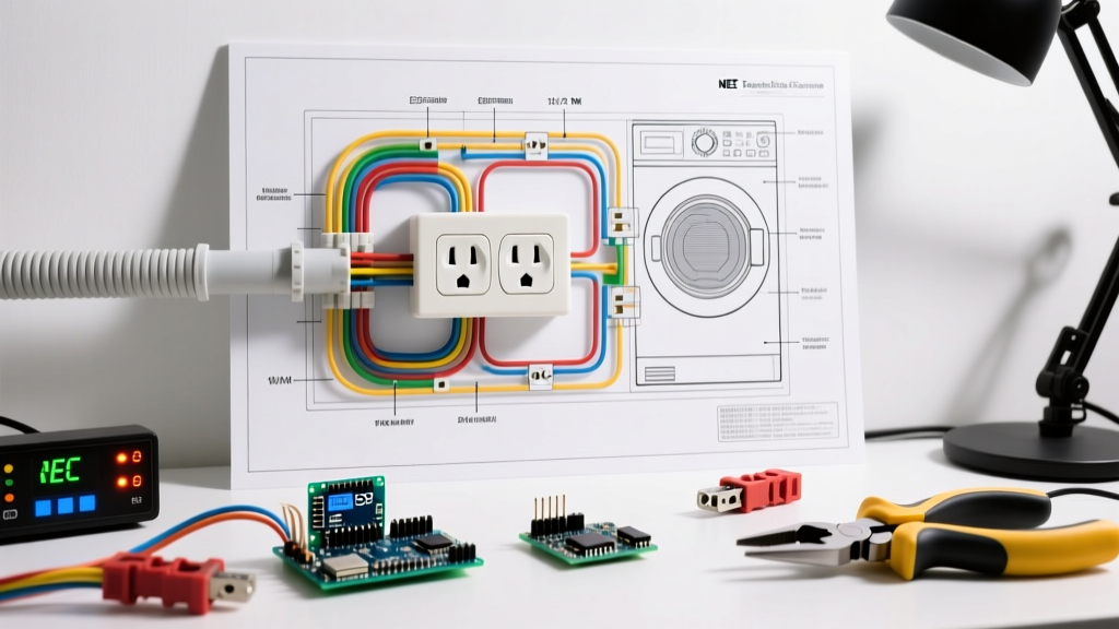

Decoding the Modern Wiring Diagram for Electric Dryer Installations
Installing a 240-volt appliance requires strict adherence to electrical safety standards. A proper wiring diagram for electric dryer circuits is not just about making the machine spin; it is about managing high-amperage loads, preventing thermal runaway, and ensuring life-safety grounding. According to the U.S. Consumer Product Safety Commission (CPSC), clothes dryers are responsible for thousands of residential fires annually, with electrical failures and improper wiring ranking among the leading causes.
As of 2026, the National Electrical Code (NEC) mandates specific configurations for dryer circuits, completely phasing out legacy 3-prong setups in new construction. This guide provides a comprehensive, code-compliant wiring diagram for electric dryer installations, detailing exact component specifications, terminal mappings, and torque requirements to ensure a flawless, inspector-ready setup.
Core Circuit Architecture: The 4-Prong Mandate
Historically, dryers utilized a 3-prong NEMA 10-30 configuration, which combined the neutral and ground paths. This created a dangerous scenario where return current could energize the dryer’s metal chassis if the neutral wire failed. The NEC addressed this via Article 250.140, which explicitly forbids using the grounded conductor (neutral) for grounding equipment on the load side of the service disconnect for new installations.
Today, the universal wiring diagram for electric dryer circuits relies on the NEMA 14-30 4-prong standard. This configuration separates the current-carrying neutral from the equipment grounding conductor (EGC), ensuring that the chassis remains at zero potential even during a fault condition.
NEC 2023/2026 Compliance Note: Under NEC Article 422.31, an appliance must have a dedicated disconnecting means. For hardwired dryers, a 30-amp breaker serves as this disconnect. For cord-and-plug connected dryers, the NEMA 14-30P plug itself acts as the disconnecting means, provided it is accessible.
Component Sizing & Material Matrix
Selecting the correct materials is critical. Undersized wire causes voltage drop and insulation melting, while oversized breakers fail to protect the conductors. Below is the definitive sizing matrix for a standard 5.5 kW to 7.0 kW residential electric dryer.
| Component | Specification | 2026 Avg. Cost | Code Reference |
|---|---|---|---|
| Circuit Breaker | 30A, 2-Pole (e.g., Eaton BR230 or Square D HOM230) | $12 - $18 | NEC 210.20(A) |
| Wire (Standard Run) | 10 AWG Copper, 3-Conductor + Ground (10/3 NM-B) | $1.65 / ft | NEC 310.16 |
| Wire (Long Run >100ft) | 8 AWG Copper, 3-Conductor + Ground (8/3 NM-B) | $2.85 / ft | NEC 310.15(B) (Voltage Drop) |
| Receptacle | NEMA 14-30R, 125/250V, 30A (e.g., Leviton 278-S00) | $15 - $22 | NEC 406.4 |
| Plug / Cord | NEMA 14-30P, 4-Prong, 30A, 125/250V (4-wire SRDT) | $25 - $35 | UL 817 / NEC 422.16 |
Terminal Block Mapping: Step-by-Step Connection Guide
When wiring the receptacle and the dryer’s terminal block, precision is non-negotiable. The standard color code for a 4-wire dryer circuit is Black (L1), Red (L2), White (Neutral), and Bare/Green (Ground).
1. Wiring the NEMA 14-30R Receptacle
- X (Left Brass): Connect the Black (L1) hot wire. This carries 120V relative to neutral.
- Y (Right Brass): Connect the Red (L2) hot wire. This carries the opposing 120V phase, yielding 240V across X and Y.
- W (Silver Center): Connect the White (Neutral) wire. This carries the unbalanced 120V return current for the dryer’s timer, motor, and control board.
- G (Green/Bottom): Connect the Bare Copper (Ground) wire. This connects directly to the panel’s ground bar and the receptacle’s metal yoke.
2. Wiring the Dryer Terminal Block
Access the dryer’s rear terminal block by removing the access plate. You will see three or four screws, plus a chassis grounding screw.
- Left Outer Screw (L1): Attach the Black wire.
- Right Outer Screw (L2): Attach the Red wire.
- Center Screw (N): Attach the White wire.
- Chassis Ground Screw (G): Attach the Green wire from the cord. Critical: Ensure this connects to the dryer’s metal frame, not the terminal block.
Critical Safety Step: Removing the Neutral-Ground Bond
If you are installing a 4-prong cord on a dryer that shipped with a 3-prong cord (or was previously wired for one), you must remove the bonding strap. This copper or brass tab connects the center neutral terminal to the dryer’s metal chassis.
The Hazard: If the bonding strap is left in place on a 4-prong system, neutral return current will split between the white wire and the green ground wire. This energizes the grounding system, creating a severe shock hazard and violating NEC Article 250.6(A), which prohibits objectionable current on grounding conductors.
Long-Run Voltage Drop Calculations
The NEC recommends a maximum voltage drop of 3% for branch circuits. For a 240V dryer circuit, the maximum allowable drop is 7.2 volts. Standard 10 AWG copper wire has a resistance of approximately 1.24 ohms per 1,000 feet.
If your electrical panel is located more than 100 feet from the laundry room, 10/3 NM-B wire will exceed the 3% voltage drop threshold when the dryer’s heating element (which can draw up to 22 amps) engages. This causes the heating coils to underperform, extending dry times and degrading the motor’s lifespan due to low-voltage stress.
The Fix: Upgrade to 8/3 NM-B copper wire for any run exceeding 100 feet. While the 8 AWG wire is thicker, the NEMA 14-30R receptacle terminals and the 30A breaker lugs are rated to accept up to 8 AWG conductors, ensuring a secure mechanical connection without the need for pigtailing.
Torque Specifications & Thermal Failure Modes
According to the Electrical Safety Foundation International (ESFI), loose electrical connections are a primary catalyst for residential fires. When a terminal screw is under-torqued, the reduced surface contact area increases electrical resistance. Under a heavy 22-amp load, this resistance generates intense heat, melting the wire insulation and eventually causing an arc fault.
Proper Torque Application
Do not rely on the 'wrist-tight' method. Use a calibrated inch-pound torque screwdriver. While specific values vary by manufacturer (always check the wiring schematic glued to the inside of the dryer’s access panel), the industry standard for 10 AWG copper on dryer terminal blocks is 35 to 50 inch-pounds.
- Receptacle Terminals: 45 in-lbs (Typical for Leviton/Hubbell 30A devices).
- Breaker Lugs: 40 in-lbs (Typical for Eaton/Square D load centers).
- Dryer Terminal Block: 40 in-lbs.
Troubleshooting Common Installation Failures
Even with the correct wiring diagram for electric dryer setups, installers occasionally encounter edge cases. Here is how to diagnose the most frequent post-installation issues:
1. Dryer Tumbles but Produces No Heat
Diagnosis: One of the two hot legs (L1 or L2) is dead. The motor and timer operate on 120V (L1 to Neutral), but the heating element requires 240V (L1 to L2). Check the 2-pole breaker to ensure both poles are fully seated and making contact with the panel bus bars. Test the receptacle with a multimeter; you should read 120V from X to W, 120V from Y to W, and 240V from X to Y.
2. Breaker Trips Immediately Upon Start
Diagnosis: This indicates a dead short or a severe ground fault. Verify that the neutral-ground bonding strap was removed (if using a 4-prong cord). Inspect the cord for pinch points where it enters the dryer’s rear strain relief bracket; a crushed cord will cause the hot conductors to short against the ground wire.
3. GFCI/AFCI Nuisance Tripping
Diagnosis: Modern code updates in certain jurisdictions require AFCI or GFCI protection for laundry areas. Older dryers with degraded heating elements or failing EMI filters can leak enough current to trip a 30mA GFCI breaker. If nuisance tripping occurs on a new, code-compliant breaker, test the dryer’s heating element for continuity to ground using a megohmmeter (megger). Any reading below 1 Megohm indicates a failing element that must be replaced.
Final Inspection Checklist
Before energizing the circuit and pushing the dryer into its final alcove, verify the following:
- Breaker is OFF during all termination work.
- Wire insulation is stripped exactly 3/4 inch, with no exposed copper visible outside the terminal clamps.
- Ground wire is securely terminated to the panel’s dedicated ground bar, not the neutral bar (unless it is the main service disconnect panel).
- Strain relief clamp is tightly secured over the dryer cord’s thick rubber jacket, not the individual wire insulation.
- Multimeter confirms 240V across L1 and L2 before connecting the appliance cord.
By strictly following this wiring diagram for electric dryer configurations and adhering to the latest NEC safety mandates, you ensure a high-performance, fire-resistant installation that will safely handle the rigors of daily use for decades.