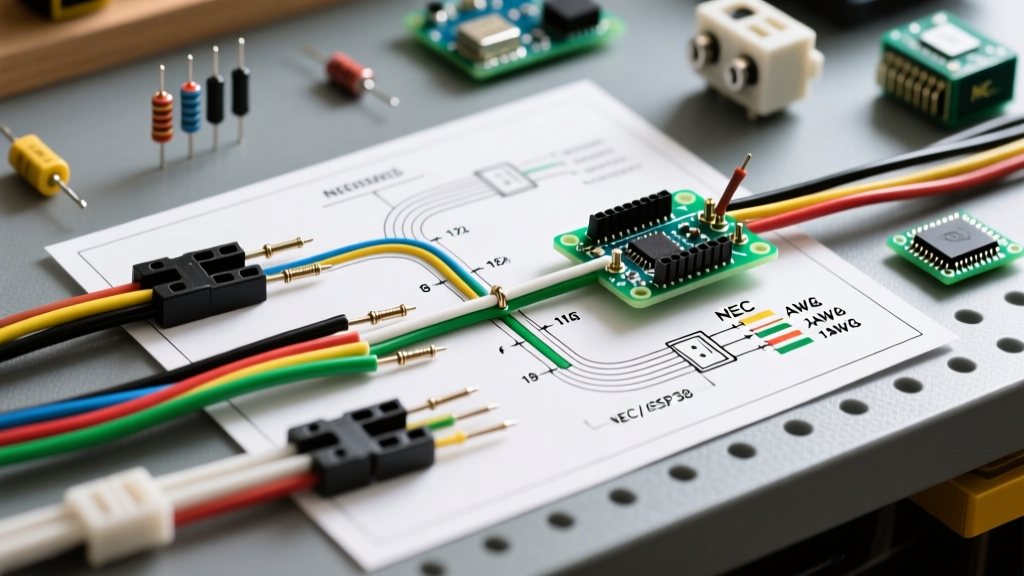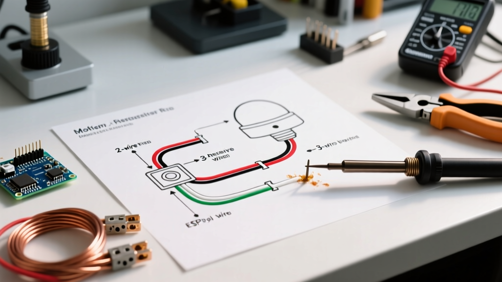

Understanding the Core Wiring Diagram for Motion Sensor Light Setups
Upgrading to automated lighting is one of the most effective ways to reduce residential and commercial energy consumption. According to the U.S. Department of Energy, integrating occupancy sensors can reduce lighting energy use by 30% to 50% in commercial spaces and up to 30% in residential zones. However, the transition from a standard single-pole toggle to an active electronic sensor requires a precise understanding of line, load, neutral, and ground connections.
In 2026, the vast majority of new LED fixtures require specific wiring configurations to prevent 'ghosting' (flickering) and ensure the sensor's internal relay receives adequate standby power. This comprehensive walkthrough breaks down the exact wiring diagram for motion sensor light switches, covering both 3-wire (with neutral) and 2-wire (no neutral) configurations.
⚠️ CRITICAL SAFETY WARNING: Always turn off power at the main breaker panel and verify zero voltage with a Category III digital multimeter before opening any junction box. Never rely solely on a non-contact voltage tester, as phantom voltages can cause false readings.Identifying Your Switch Type: 2-Wire vs. 3-Wire Requirements
Before pulling any wires, you must determine which wiring diagram for your motion sensor light applies to your existing electrical box. The National Electrical Code (NEC) Article 404.2(C) now mandates that new construction switch boxes include a neutral wire to accommodate electronic lighting controls. However, older homes built before 2011 often lack this neutral wire at the switch location.
| Feature | 3-Wire (With Neutral) | 2-Wire (No Neutral) |
|---|---|---|
| Industry Standard Model | Leviton DOS05 (Eco-View) | Lutron MS-OPS2 (Maestro) |
| Wires Required | Line (Black), Load (Red), Neutral (White), Ground | Line (Black), Load (Red/Black), Ground |
| Minimum Load | 0 Watts (Handles single 5W LEDs) | Typically 10W-15W minimum (without capacitor) |
| LED Flicker Risk | Virtually Zero | High (Requires bypass capacitor for low loads) |
| Average Retail Cost (2026) | $38 - $45 USD | $28 - $35 USD |
Step-by-Step Walkthrough: 3-Wire (With Neutral) Installation
The 3-wire setup is the gold standard for modern motion sensor installations. Because the sensor draws its standby power directly from the line and neutral, it does not leak current through the lighting load, completely eliminating LED ghosting.
Phase 1: Preparation and Wire Stripping
- Verify Power Off: Test the existing switch with a multimeter. Set to AC Voltage (V~) and measure between the black wire and the bare ground. It must read 0.0V.
- Remove Old Switch: Unscrew the terminal screws. Do not cut the wires; back them out to preserve wire length in the box.
- Strip and Condition: If the existing copper is oxidized or damaged, snip the ends and strip exactly 3/4 inch of insulation from the 14 AWG or 12 AWG wires. Use a wire stripper with a built-in gauge to avoid nicking the copper conductor, which creates a high-resistance hot spot.
Phase 2: Making the Connections
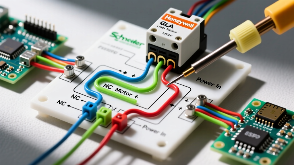
Referencing the Leviton DOS05 specification sheet, follow this exact termination sequence:
- Ground (Green/Bare): Connect the bare copper or green insulated ground wire from the wall to the green ground screw on the sensor. Torque to 14 in-lbs if using a calibrated screwdriver.
- Neutral (White): Connect the sensor's white wire to the bundle of white neutral wires in the back of the box. Crucial Note: Do not connect the sensor's white wire to the white wire of the light fixture cable unless you have positively identified it as the source neutral using a continuity test.
- Line / Hot (Black): Identify the constantly hot wire (usually black) using a voltage tester before turning the power off. Connect this to the sensor's black 'Line' wire.
- Load (Red): Connect the sensor's red wire to the remaining wire in the box (the 'Load' or 'Switched Hot' returning to the light fixture).
Pro-Tip: Abandon twist-on wire nuts for this step. Use Wago 221 3-port lever connectors. They provide a gas-tight connection, accommodate both 12 and 14 AWG solid/stranded wire simultaneously, and allow for easy voltage testing via the integrated test ports.
Step-by-Step Walkthrough: 2-Wire (No Neutral) & The Ghosting Fix
If your junction box only contains a black, white (used as a switched hot), and bare ground, you must use a 2-wire motion sensor like the Lutron MS-OPS2. In this wiring diagram for your motion sensor light, the sensor completes its internal circuit by passing a tiny trickle of current (approx. 1mA) through the light bulb itself.
The 'Ghosting' Failure Mode
Because modern LED bulbs draw so little power, the 1mA trickle current can charge the LED's internal driver capacitor. Once charged, the LED flashes or glows dimly—a phenomenon known as ghosting. To fix this, you must install a LUT-MLC Bypass Capacitor at the light fixture.
Installation Steps for 2-Wire + Capacitor
- Switch Box Wiring: Connect the sensor's black wire to the wall's Line (Hot). Connect the sensor's second wire (often black with a blue sleeve or just a second black) to the wall's Load. Connect the ground.
- Fixture Box Wiring (Capacitor Install): Go to the actual light fixture on the ceiling. Locate the black (hot) and white (neutral) wires feeding the socket.
- Install LUT-MLC: Wire the LUT-MLC capacitor in parallel across the light fixture's input wires. Connect one lead of the capacitor to the fixture's black wire, and the other lead to the fixture's white wire. Secure with Wago connectors.
- Test: Restore power. The capacitor acts as a sink for the trickle current, preventing the LED driver from charging and eliminating the flicker.
Sensor Calibration and Placement Edge Cases
Wiring the device correctly is only half the battle. Improper calibration leads to false triggers or premature shutoffs, which frustrates users and defeats the purpose of the upgrade.
Avoiding False Triggers (PIR Sensor Limitations)
Passive Infrared (PIR) sensors detect changes in heat signatures. In 2026, while sensor algorithms have improved, physical placement remains critical:
- HVAC Vents: Never mount a motion sensor within 6 feet of an HVAC supply register. The sudden blast of hot or cold air will trigger the PIR element, keeping the lights on indefinitely.
- Direct Sunlight: Avoid line-of-sight to west-facing windows. The rapid thermal shift of a passing cloud or setting sun can cause phantom activations.
- Pet Immunity: If using a sensor in a room with large dogs (over 40 lbs), ensure the sensor is mounted at least 6.5 feet high and angle the lens slightly upward using the adjustment collar to mask the floor zone.
Setting the Time-Out and Sensitivity Dials
Most premium sensors feature hidden potentiometers or dip-switches behind the faceplate. For a standard residential hallway or bathroom:
- Time-Out: Set to 5 minutes. (1 minute is too short and causes annoying shut-offs while a user is stationary on the toilet or reading; 15+ minutes wastes energy).
- Sensitivity: Set to 'Medium' or '50%'. Maximum sensitivity will trigger the light if a person walks in the adjacent hallway past an open door.
- Ambient Light Override (Photocell): Enable this feature if the room receives natural daylight. This prevents the lights from turning on when motion is detected if the room already has >30 foot-candles of ambient light.
NEC Compliance and Code Considerations
When consulting any wiring diagram for motion sensor light setups, you must adhere to the National Fire Protection Association (NFPA) NEC guidelines. Specifically, ensure that your motion sensor switch is rated for the exact load type you are controlling.
If you are controlling a motorized exhaust fan (like a bathroom vent fan), you cannot use a standard lighting motion sensor. You must use a sensor specifically rated for inductive/ballast loads (e.g., Lutron MS-OPS5MH-DV). Standard LED-rated sensors use solid-state triacs or small relays that will weld shut or overheat when subjected to the high inrush current of an electric motor. Always check the 'Load Rating' matrix on the side of the device packaging before installation.
Frequently Asked Questions
Can I use a motion sensor switch on a 3-way circuit?
Yes, but it requires specific hardware. You cannot simply wire two motion sensors together in a standard 3-way traveler configuration. You must use a master/add-on system (like the Leviton DZS15 paired with a DD0SR companion), or use a single motion sensor wired to control a smart relay at the fixture while keeping the secondary 3-way switch as a manual override.
Why does my motion sensor click constantly but the light won't turn on?
This indicates a failed internal relay or a burnt-out triac, usually caused by an inrush current overload. If the switch was used to control a bank of commercial LED high-bays without a soft-start driver, the initial current spike likely destroyed the switching component. Replace the switch and ensure the total connected LED wattage does not exceed 60% of the switch's maximum rated incandescent wattage to provide a safety margin for inrush currents.
Do I need to cap the unused neutral wire on a 2-wire switch?
Yes. If you are installing a 2-wire (no neutral required) sensor into a modern box that actually does have a neutral wire present, you must cap the switch's unused white neutral wire with a wire nut. Do not leave it exposed, and do not connect it to the ground wire, as this will create a dead short and trip the breaker immediately.