
Understanding the Starter Solenoid's Role in Small Engines
When you turn the ignition key on a riding lawn mower, the ignition switch cannot handle the massive electrical current required to crank the engine. This is where the starter solenoid comes in. Acting as a heavy-duty electromagnetic relay, the solenoid uses a low-current signal from the ignition switch to close a high-current circuit between the 12V battery and the starter motor. Understanding the exact starter solenoid wiring diagram for lawn mower applications is critical for safe, reliable repairs, especially as modern 2026 models integrate complex safety interlocks and electronic fuel injection (EFI) systems that are highly sensitive to voltage drops.
Whether you are repairing a vintage Craftsman tractor or a modern John Deere zero-turn, the fundamental physics remain the same. However, incorrect wiring can lead to parasitic battery drains, melted wiring harnesses, or bypassed safety switches. According to the Oregon State University Extension, improper electrical repairs are a leading cause of small engine fires and premature starter motor failure due to sustained voltage starvation.
3-Post vs. 4-Post Solenoids: Identifying Your Hardware
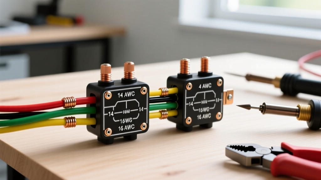
Before routing any wires, you must identify which type of solenoid your mower requires. Using the wrong type will result in a dead short or a failure to crank. OEM replacements from brands like Stens, Oregon, or Rotary typically cost between $14 and $28 in 2026, making it cost-effective to simply buy the correct unit rather than adapting the wrong one.
| Feature | 3-Post Solenoid (Case Ground) | 4-Post Solenoid (Isolated Ground) |
|---|---|---|
| Large Terminals | 2 (Battery In, Starter Out) | 2 (Battery In, Starter Out) |
| Small Terminals | 1 (Ignition Trigger 'S') | 2 (Ignition Trigger 'S', Ground 'G') |
| Grounding Method | Grounds through the metal mounting bracket to the mower frame. | Requires a dedicated ground wire from the 'G' terminal to the battery negative or frame. |
| Best Application | Older mowers with clean, bare-metal mounting surfaces. | Modern mowers with painted frames, plastic mounting tabs, or high-vibration environments. |
Expert Warning: Never attempt to wire a 4-post solenoid into a 3-post harness without adding a dedicated ground wire to the second small terminal. Leaving the ground terminal floating will prevent the internal electromagnet from engaging, resulting in a silent no-crank condition.
Required Tools and Wire Gauge Specifications
A common mistake in DIY appliance and mower wiring is using undersized wire or improper termination methods. The starter circuit draws between 150 and 300 amps momentarily. Standard household wire or thin automotive wire will melt instantly.
- High-Current Cables (Battery to Solenoid, Solenoid to Starter): Use 8 AWG or 10 AWG SAE J1128 GXL (Cross-linked) stranded copper wire. GXL insulation resists high engine bay temperatures and abrasive vibration.
- Low-Current Trigger Wire (Ignition to Solenoid): 14 AWG or 16 AWG stranded copper. This circuit only draws 2 to 5 amps.
- Terminals: 5/16-inch ring terminals for the large posts; 1/4-inch spade or ring terminals for the small trigger posts. Use heat-shrink insulated terminals to prevent shorting against the mower deck.
- Crimping Tool: Use a hex-crimp or indent-crimp tool. Never solder high-current battery cables. Solder is brittle and will crack under the high-frequency vibration of a single-cylinder or V-twin lawn mower engine, leading to high resistance and arcing.
- Multimeter: Required for voltage drop testing and verifying safety switch continuity.
Step-by-Step Starter Solenoid Wiring Diagram for Lawn Mower
Follow this exact sequence to ensure safety and proper circuit logic. Always disconnect the negative (black) battery terminal before beginning any electrical work.
Phase 1: High-Current Routing (The Load Circuit)
- Mount the Solenoid: Secure the solenoid to the frame using stainless steel hardware. If using a 3-post solenoid, ensure the mounting surface is sanded down to bare metal to guarantee a solid chassis ground. Apply dielectric grease to the mating surface to prevent future corrosion.
- Battery to Solenoid: Connect a heavy-gauge (8-10 AWG) red cable from the positive terminal of the 12V battery to one of the large copper posts on the solenoid. Torque the nut to 50-70 in-lbs.
- Solenoid to Starter Motor: Connect a second heavy-gauge red or black cable from the remaining large copper post on the solenoid directly to the positive terminal on the starter motor.
Phase 2: Low-Current Routing (The Control Circuit)
- Ignition Trigger: Locate the 'Start' wire coming from the ignition switch (typically white or red with a white stripe on modern harnesses). Attach this to the small terminal marked 'S' or 'I' on the solenoid. This wire should pass through a 10-amp inline fuse near the ignition switch.
- Grounding the Coil (4-Post Only): If using a 4-post solenoid, attach a 14 AWG black wire from the small terminal marked 'G' to a clean, unpainted metal point on the engine block or directly to the battery negative terminal.
- Reconnect Battery: Reattach the negative battery cable last to prevent accidental shorting while tightening the high-current posts.
Integrating OEM Safety Interlocks (PTO and Brake)
Modern riding mowers are governed by strict safety standards. The U.S. Consumer Product Safety Commission (CPSC) mandates that starter circuits must be interrupted if the mower blades are engaged or if the operator is not in the seat. Your starter solenoid wiring must integrate these safety switches seamlessly.
In most 2026 wiring diagrams, the safety switches are wired in series on the ground side of the solenoid coil (for 4-post setups) or on the trigger side (for 3-post setups). For example, the ignition 'Start' signal passes through the brake pedal switch (normally open, closes when pressed) and the PTO switch (normally closed, opens if blades are engaged) before reaching the solenoid's 'S' terminal. If you bypass these switches by wiring the ignition directly to the solenoid, you create a severe laceration hazard and violate federal safety guidelines.
Diagnostic Matrix: Solenoid Failure Modes
Even with a perfect starter solenoid wiring diagram for your lawn mower, components degrade. Use this diagnostic matrix to troubleshoot issues without blindly replacing parts.
| Symptom | Probable Cause | Diagnostic Action |
|---|---|---|
| Rapid Clicking, No Crank | Voltage drop in high-current cables or weak battery. | Perform a voltage drop test across the solenoid while cranking. A drop greater than 0.2V indicates corroded terminals or undersized wire. |
| Silent No-Crank | Blown inline fuse, open safety switch, or dead coil. | Check for 12V at the 'S' terminal while holding the key in 'Start'. If 12V is present but solenoid doesn't click, the internal coil is open. |
| Continuous Cranking (Key Off) | Welded internal copper contacts. | Immediately disconnect the battery negative cable. The high amperage has melted the contacts together. Replace the solenoid; do not attempt to repair. |
| Starter Spins, Engine Doesn't Turn | Bendix gear failure or stripped starter ring gear. | This is a mechanical starter issue, not a solenoid wiring issue. Inspect the starter motor drive clutch. |
For deeper electrical diagnostics, including testing the stator and alternator output that keeps the battery charged between cranks, refer to the Briggs & Stratton Support FAQs, which provide model-specific multimeter testing parameters for their Vanguard and Intek engine lines.
Final Thoughts on Mower Electrical Safety
Mastering the starter solenoid wiring diagram for your lawn mower is about more than just getting the engine to turn over; it is about ensuring the high-current paths are secure and the safety interlocks remain fully functional. Always use hex-crimped, heat-shrink sealed terminals, verify your 3-post vs 4-post configuration, and never bypass the PTO or seat safety switches. By adhering to these professional standards, your mower's starting system will provide reliable, safe service for years to come.