
The Hidden Culprits Behind Air Suspension Failures
When an air suspension system fails, most DIYers and even some professional technicians immediately suspect a leaking airbag or a burnt-out air compressor. However, real-world diagnostic data reveals that nearly half of all air ride faults originate in the electrical harness, relay circuits, or sensor feedback loops. Whether you are maintaining a factory OEM setup on a late-model Ford Expedition or tuning an aftermarket Air Lift Performance 3H management system, possessing and understanding the correct wiring diagram for air ride suspension is the single most critical step in accurate, cost-effective diagnostics.
In this comprehensive guide, we will decode the electrical architecture of modern air suspension systems, map out standard wiring color codes and gauges, and provide step-by-step multimeter troubleshooting scenarios based directly on schematic tracing. By the end of this article, you will be able to isolate a parasitic draw, identify a failed PWM solenoid, or diagnose a 5V reference failure in minutes rather than hours.
Core Electrical Architecture: The 4 Main Nodes
Before diving into the schematic, you must understand the four primary electrical nodes that govern any air ride system. A standard wiring diagram for air ride suspension will route power and data between these components:
- The Control Module (ECU): The brain of the system. It reads sensor inputs and triggers relays or solenoids. In aftermarket kits like the AccuAir VU4 or Air Lift 3H, this module also handles Bluetooth telemetry and app-based presets.
- The Compressor and Relay Assembly: Heavy-draw components. Compressors like the Viair 444C or 480C can pull 30 to 45 amps under load, necessitating high-amperage relays and thick-gauge power wiring.
- Solenoid Valves (Manifold): Electrically actuated gates that direct airflow. Modern proportional valves use Pulse Width Modulation (PWM) rather than simple on/off 12V signals.
- Height Sensors (Ride Height Sensors): Potentiometers or Hall-effect sensors mounted to the suspension control arms. They provide real-time feedback to the ECU to maintain the target ride height.
Decoding the Wiring Diagram: Gauges, Colors, and Standards
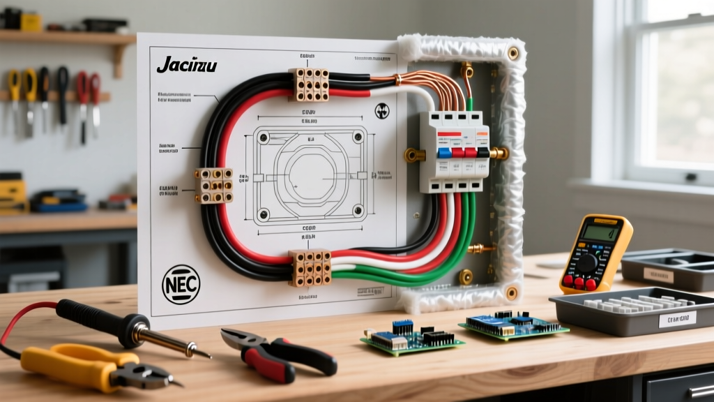
Automotive wiring diagrams use standardized line weights and color codes to represent wire gauge and function. When working under the hood or beneath the chassis, wires are exposed to extreme heat, moisture, and vibration. According to the SAE J1128 Standard for Low Tension Primary Cable, under-hood wiring must utilize specific insulation types (like cross-linked polyethylene) to resist melting against exhaust components.
Below is a reference matrix mapping typical circuit functions to their required wire gauges, standard aftermarket color codes, and protection ratings.
| Circuit Function | Typical Wire Gauge (AWG) | Color Code (Aftermarket) | Fuse / Breaker Rating | Diagnostic Note |
|---|---|---|---|---|
| Compressor Main Power | 10 AWG or 8 AWG | Red | 40A Inline Circuit Breaker | Voltage drop must be < 0.2V at full load. |
| Relay Trigger (from ECU) | 18 AWG | Blue / White Stripe | 5A Mini Fuse | Check for 12V only when ECU commands fill. |
| Solenoid Valve PWM | 16 AWG | Green / Yellow | 15A | Requires oscilloscope to read duty cycle. |
| Height Sensor 5V Reference | 20 AWG (Shielded) | Purple (Signal) / Black (Ground) | 2A (Internal ECU protection) | Highly susceptible to EMI from alternators. |
Multimeter Diagnostics: 3 Common Wiring Scenarios
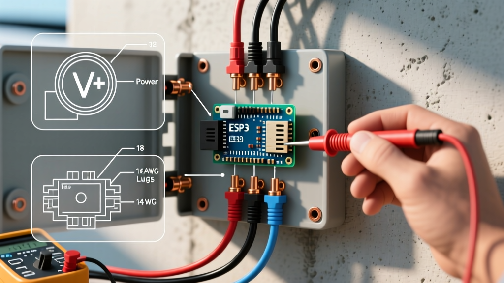
A wiring diagram is only as useful as your ability to test the physical wires against it. Grab your digital multimeter (DMM) and follow these targeted diagnostic flows.
Scenario A: The Compressor Runs Continuously (Never Shuts Off)
The Symptom: The compressor runs until it hits its thermal overload switch, or it drains the battery overnight.
The Diagram Trace: Look at the relay control circuit on your wiring diagram. The ECU grounds the relay coil (Pin 85) to activate the compressor. If the compressor won't shut off, the relay is either mechanically welded shut, or the ECU is stuck sending a ground signal.
- Isolate the Relay: Pull the 30A compressor relay from its socket. If the compressor immediately stops running, the relay contacts (Pins 30 and 87) were internally welded together due to arcing. Fix: Replace the Bosch-style relay ($12 - $25).
- Test the ECU Trigger: If the compressor still runs with the relay removed, you have a severe short to power on the load side of the relay, or a bypassed circuit. Consult the diagram to trace the 10 AWG red wire from the relay output to the compressor motor for chafed insulation touching the chassis.
Scenario B: Compressor Won't Turn On (Dead Circuit)
The Symptom: The vehicle is sagging on one corner or the entire axle, but the compressor is silent.
The Diagram Trace: Power flows from the battery to the fuse, to Relay Pin 30. The ECU sends a 12V trigger to Relay Pin 86. The relay coil grounds at Pin 85.
- Verify Main Power: Set your DMM to DC Volts. Probe Relay Pin 30 to chassis ground. You should read 12.6V. If 0V, check the main 40A inline fuse or circuit breaker.
- Test the Coil Trigger: Reinsert the relay. Back-probe Pin 86 with the ignition ON and the suspension switch set to 'Raise'. You should see 12V. If missing, trace the 18 AWG trigger wire back to the ECU or dashboard switch for an open circuit.
- Check the Ground: Probe Pin 85. A bad ground will prevent the magnetic coil from energizing. Perform a voltage drop test across the ground wire; it should read less than 0.1V.
Scenario C: One Corner Won't Inflate (Solenoid or Sensor Fault)
The Symptom: The compressor runs, three corners rise, but the rear-left corner remains dropped.
The Diagram Trace: Trace the specific solenoid valve wire (e.g., Green/Yellow) from the ECU to the manifold. Modern manifolds use PWM signals to gently fill the bag and prevent harsh bouncing.
Expert Warning on PWM Diagnostics: If you probe a PWM solenoid wire with a standard multimeter, you will see a fluctuating, seemingly random DC voltage (e.g., jumping between 4V and 9V). This does not necessarily mean the wire is bad. To accurately diagnose a PWM circuit shown on your wiring diagram, you need an automotive oscilloscope to verify the square wave pattern and duty cycle, or an advanced bidirectional scan tool to command the valve open while listening for the physical 'click' at the manifold.
Resistance Test: Disconnect the manifold plug. Set your DMM to Ohms (200 setting). Probe the solenoid pins. A healthy air solenoid typically reads between 10 and 25 ohms. An infinite reading (OL) indicates a blown internal coil, requiring a manifold rebuild or replacement.
Height Sensor Calibration and Signal Dropouts
Height sensors are the most fragile electrical components in an air ride setup. They are mounted near the wheel wells, constantly bombarded by road debris, water, and salt. According to diagnostic bulletins from Air Lift Performance Support, improper linkage adjustment and sensor wire chafing account for the majority of 'false height' error codes.
The wiring diagram will show a 3-wire harness for each sensor:
- Wire 1 (5V Reference): Supplied by the ECU. Must read exactly 4.8V to 5.1V.
- Wire 2 (Ground): Sensor return path.
- Wire 3 (Signal): The feedback wire. As the suspension compresses, voltage drops (e.g., 0.5V). As it extends, voltage rises (e.g., 4.5V).
The Sweep Test: Jack up the vehicle and let the suspension hang. Disconnect the sensor arm from the control arm. Slowly rotate the sensor arm through its full range of motion while back-probing the signal wire. Watch your multimeter. The voltage should sweep smoothly. If the voltage suddenly drops to 0V or spikes to 5V mid-sweep, the internal potentiometer track is damaged. Replace the sensor ($45 - $120 depending on OEM vs. aftermarket).
Component Replacement & Cost Guide (2026 Estimates)
When your diagram tracing confirms a failed component, sourcing high-quality replacements is vital. Cheap relays and undersized wire will lead to repeat failures and potential fire hazards.
| Component | OEM / High-End Aftermarket | Budget / Generic | Installation Tip |
|---|---|---|---|
| Heavy Duty Relay Harness | $65 - $95 (Air Lift / Viair) | $25 - $40 | Always use a harness with an inline 40A breaker, not a standard blade fuse. |
| Ride Height Sensor | $110 - $250 (OEM Motorcraft/ACDelco) | $40 - $70 | Apply dielectric grease to the connector to prevent galvanic corrosion. |
| Solenoid Valve Rebuild Kit | $85 - $150 (AccuAir / Air Lift) | N/A | Clean the manifold block with compressed air before installing new O-rings. |
| Shielded Sensor Wire (per ft) | $3.50 - $5.00 | $1.50 - $2.50 | Never run sensor wires parallel to ignition coils or alternator outputs. |
Final Best Practices for Harness Routing
Even with a perfect wiring diagram for air ride suspension, poor physical installation will doom the system. When repairing or extending wires, adhere to the standards outlined by automotive electrical certification bodies like ASE (Automotive Service Excellence). Never use twist-on wire nuts or standard electrical tape under the hood. Instead, use adhesive-lined heat shrink tubing and crimp connectors. Route all wiring harnesses away from exhaust manifolds, steering shafts, and shock absorbers, securing them with UV-resistant zip ties every 6 to 8 inches. By combining schematic literacy with rigorous physical testing, you can conquer any air suspension electrical gremlin with confidence.