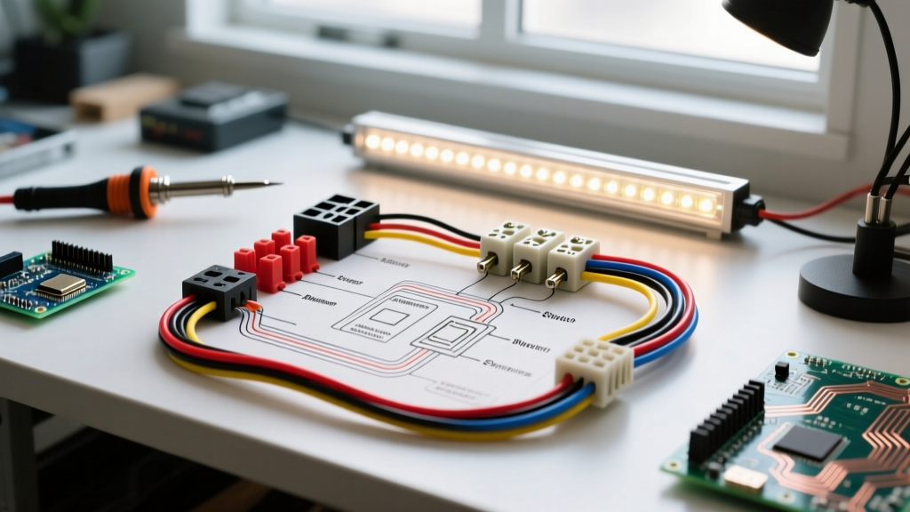

The Complete Wiring Diagram for a LED Light Bar: Why a Relay is Mandatory
Installing a high-output LED light bar is one of the most popular off-road modifications, but improper wiring remains the leading cause of melted switches, voltage drop, and even vehicle fires. A standard 50-inch, 300W LED light bar draws approximately 25 amps at 12 volts. Routing this amperage directly through a dashboard toggle switch and factory 18-gauge dash wiring will overwhelm the circuit, causing severe voltage drop and generating enough heat to melt the switch housing.
To safely deliver maximum luminosity and protect your vehicle's electrical system, you must use a relay harness. This step-by-step wiring diagram for a LED light bar will walk you through routing a heavy-duty 12 AWG power circuit directly from the battery, using a standard 40A Bosch-style relay to handle the high amperage, while your dashboard switch only handles a minimal 0.5A trigger signal.
Component Selection and Wire Gauge Sizing
Before cutting any wire, you must select the correct materials. Do not use standard THHN building wire from a hardware store. Automotive environments require SAE J1128 GXL or TXL cross-linked polyethylene (XLPE) wire, which withstands under-hood temperatures up to 125°C (257°F) and resists oil, grease, and solvent degradation.
| Light Bar Wattage | Approx. Amp Draw (12V) | Main Power Wire (AWG) | Trigger Wire (AWG) | Inline Fuse Size |
|---|---|---|---|---|
| Up to 120W | 10A | 14 AWG | 18 AWG | 15A ATO Blade |
| 121W - 240W | 10A - 20A | 12 AWG | 16 AWG | 20A ATO Blade |
| 241W - 360W | 20A - 30A | 10 AWG | 16 AWG | 30A MAXI Blade |
| 361W - 500W+ | 30A - 42A+ | 8 AWG | 14 AWG | 50A MAXI / ANL |
Note: Always use the Southwire Voltage Drop Calculator to verify wire gauge if your cable run from the battery to the light bar exceeds 15 feet, as extended runs require upsizing the wire to prevent a 3% or greater voltage drop.
Understanding the 4-Pin Relay Architecture
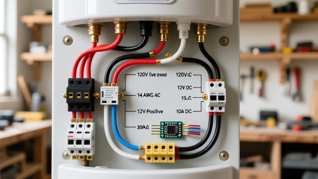
The core of this wiring diagram for a LED light bar relies on a standard ISO Mini 4-pin relay (commonly manufactured by Bosch, Hella, or Tyco). Understanding the pinout is critical for troubleshooting:
- Pin 30 (Common): High-amperage 12V power IN from the battery.
- Pin 87 (Normally Open): High-amperage 12V power OUT to the LED light bar.
- Pin 86 (Coil Power): Low-amperage 12V trigger signal IN from your dashboard switch.
- Pin 85 (Coil Ground): Ground for the internal electromagnet coil.
Step-by-Step Wiring Walkthrough
Step 1: The Main Power Feed and Fuse Placement
Begin by measuring and cutting your main power wire (e.g., 12 AWG red XLPE) to run from the battery positive terminal to the relay location. Critical Safety Rule: You must install an inline fuse holder on this main power wire within 18 inches of the battery positive terminal. This protects the entire length of the wire in the event of a short circuit against the chassis. Strip the ends, crimp on high-quality ring terminals using a ratcheting crimper (like the Titan 11470), and apply adhesive-lined heat shrink to seal out moisture.
Step 2: Routing Power to the Light Bar (Pin 87)
Connect a second length of 12 AWG red wire to Pin 87 on the relay socket. Route this wire through the firewall or grill to the mounting location of your LED light bar. At the light bar, crimp on a weather-pack connector or a Deutsch DT plug. Avoid using cheap spade connectors for exterior lighting, as vibration and water ingress will cause rapid corrosion and arcing.
Step 3: Grounding the Relay and Light Bar (Pin 85)
Connect 12 AWG black wire to Pin 85. Route this to a clean, unpainted metal surface on the chassis. Use a wire brush or sandpaper to remove clear coat, paint, and rust down to bare metal. Bolt the ring terminal down securely, then coat the connection with dielectric grease to prevent galvanic corrosion. Run a separate, equally robust ground wire from the LED light bar's negative terminal directly to the chassis or back to the battery negative terminal.
Step 4: The Trigger Circuit and Switch Integration (Pin 86)
This is where the wiring diagram for a LED light bar interfaces with your cabin. Run a 16 AWG wire from Pin 86 through the firewall grommet to your dashboard switch. Connect the other side of the switch to an ignition-switched 12V source (like the radio or cigarette lighter fuse) using an Add-A-Circuit fuse tap. This ensures the light bar cannot be accidentally left on when the engine is off, preventing a dead battery.
Pro-Tip for Modern Trucks: If you are utilizing factory Upfitter Switches (AUX 1-6) in late-model trucks (2020-2026 Ford Super Duty, Ram 2500, Chevy HD), you do not need a separate relay or dashboard switch. The factory upfitter module already contains high-amperage relays. Simply connect your Pin 86 trigger wire directly to the factory upfitter output wire under the hood.
Advanced Troubleshooting: PWM Flickering and Backfeed
As vehicle electrical systems have evolved, a new issue has emerged in the off-road community: LED flickering. Modern vehicles utilize Pulse Width Modulation (PWM) to monitor auxiliary circuits. The BCM (Body Control Module) sends rapid, low-voltage pulses through the circuit to check for continuity and bulb health before applying full voltage. Because LEDs react instantly to voltage changes (unlike halogen filaments which have thermal lag), these diagnostic pulses cause the light bar to strobe or flicker when first turned on, or even when the vehicle is off.
How to Fix PWM Flickering
If your wiring diagram for a LED light bar results in flickering on a modern truck, you have two primary solutions:
- Install an Anti-Flicker Harness: These plug-and-play modules contain a large electrolytic capacitor (typically 2200µF to 4700µF) that absorbs the rapid PWM pulses and releases a steady 12V stream to the relay coil.
- Use a Solid-State Relay (SSR): Replace the mechanical Bosch mechanical relay with an automotive-grade Solid State Relay. SSRs require a specific threshold voltage to trigger and are entirely immune to low-voltage PWM diagnostic pulses.
Final Inspection and Edge Cases
Before closing the hood, perform a continuity and voltage drop test. With the light bar illuminated, use a digital multimeter to measure the voltage directly at the battery terminals, and then at the Deutsch plug on the light bar. If the difference is greater than 0.5V (e.g., 13.8V at the battery and 13.1V at the bar), you have excessive resistance. This is almost always caused by undersized wire, a poor chassis ground, or a failing crimp connection.
By strictly following this wiring diagram for a LED light bar and prioritizing automotive-grade materials over generic hardware store components, your auxiliary lighting setup will deliver maximum lumen output, survive harsh off-road vibrations, and remain entirely safe from electrical faults for the lifespan of the vehicle.