
Mastering the Wiring Diagram for a Warn Winch: A 2026 Technical Walkthrough
Installing a high-capacity winch is one of the most demanding electrical modifications you can perform on a vehicle. When pulling at maximum rated capacity, modern 12V winches can draw upwards of 350 amps, generating immense heat and requiring flawless conductivity. As of 2026, the Warn VR EVO 10-S (retailing around $749) and the premium Warn Zeon 10-S (approximately $1,299) remain the industry benchmarks for off-road recovery. However, even the best mechanical components will fail if the electrical infrastructure is undersized or improperly routed.
This guide provides a comprehensive, step-by-step walkthrough of the wiring diagram for a Warn winch, focusing on exact wire gauges, contactor logic, DC circuit protection, and real-world troubleshooting metrics. Whether you are wiring a dedicated rock crawler or a daily-driven overland rig, precise adherence to DC electrical standards is non-negotiable.
Pre-Installation Electrical Audit: The Foundation
Before unboxing the winch, you must verify that your vehicle's electrical system can handle the transient and sustained loads of a recovery operation. A standard automotive alternator produces between 80A and 150A, while a winch under load will instantly consume 200A to 350A. The deficit is pulled directly from the battery.
Minimum System Requirements for 8,000 to 12,000 lb Winches
| Component | Minimum Specification | Recommended 2026 Upgrade |
|---|---|---|
| Battery (Primary) | 650 CCA (Cold Cranking Amps) | 850+ CCA AGM or Lithium Iron Phosphate (LiFePO4) |
| Alternator Output | 80 Amps | 150A - 200A High-Output Alternator |
| Main Power Cable | 2 AWG (Up to 10ft run) | 1/0 AWG Welding Cable (SAE J1128) |
| Circuit Protection | 175A DC Breaker | 200A DC-Rated Circuit Breaker (e.g., Blue Sea Series 185) |
Expert Insight: Never use an AC-rated household breaker or a standard automotive fuse for winch circuit protection. DC arcs are continuous and do not self-extinguish at zero-crossing like AC current. Always specify a DC-rated breaker designed for high-amperage inductive loads, as recommended by Blue Sea Systems and standard marine/automotive electrical codes.
Deconstructing the Warn Winch Wiring Diagram
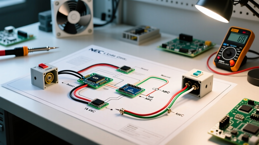
Modern Warn winches utilize a sealed, heavy-duty contactor pack rather than the legacy multi-solenoid setups found on older models. The contactor serves as a high-amperage relay, allowing the low-current wireless or wired remote to safely switch the massive current required by the series-wound or permanent magnet DC motor.
The 4-Terminal Contactor Logic
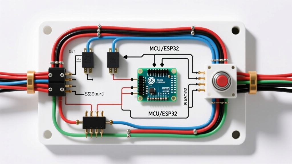
The standard Warn contactor features four large power terminals and a multi-pin logic connector. Here is how the power flows:
- Terminal 1 (Top Left): Main Power In (From Battery Positive via Breaker)
- Terminal 2 (Top Right): Motor Lead A (Typically Yellow or Red wire)
- Terminal 3 (Bottom Left): Motor Lead B (Typically Blue or Black wire)
- Terminal 4 (Bottom Right): Main Ground Out (To Battery Negative or Dedicated Chassis Ground)
When you press 'Power In' on the remote, the logic board energizes the internal coils, bridging Terminal 1 to Terminal 2, and Terminal 3 to Terminal 4, completing the circuit in one polarity. Pressing 'Power Out' reverses the bridge, swapping the polarity and reversing the motor direction.
Step-by-Step Wiring Walkthrough
Follow this exact sequence to ensure a safe, low-resistance installation. Always consult the specific schematic provided by Warn Industries for your exact model number, as logic pinouts can vary slightly between the VR EVO and Zeon lines.
Step 1: Isolate the Electrical System
Disconnect the negative battery terminal first, followed by the positive. This prevents accidental short circuits while routing the heavy-gauge cables through the engine bay. Wait 5 minutes for any secondary capacitors in vehicle ECUs to discharge.
Step 2: Mount the Contactor Pack
Locate a dry, well-ventilated area in the engine bay, at least 18 inches away from exhaust manifolds or turbocharger downpipes. The contactor generates significant heat during sustained winching. Mount it vertically with the logic connector facing downward to prevent water pooling in the weatherpack seal.
Step 3: Route and Terminate the Main Power Cables
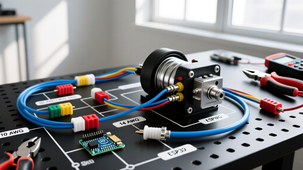
- Measure the distance from the battery positive terminal to the contactor, and from the contactor to the winch motor. Add 12 inches to your measurement for drip loops and service slack.
- Cut 2 AWG or 1/0 AWG SAE J1128 battery cable. Do not use CCA (Copper Clad Aluminum) wire; it has higher resistance and will melt under 300A loads.
- Crimp heavy-duty copper ring terminals using a hex-crimp tool. Soldering is optional but highly recommended for marine or high-humidity environments to prevent capillary corrosion.
- Wrap the cables in split-loom tubing or braided sleeving to protect against abrasion against the chassis or radiator support.
Step 4: Install the DC Circuit Breaker
Mount the 200A DC breaker within 18 inches of the battery positive terminal. Connect the winch power cable to the 'LOAD' side of the breaker, and run a short jumper cable from the 'LINE' side to the battery positive post. This ensures the entire length of the winch cable is protected against dead shorts.
Step 5: Connect the Motor Leads
Route the two motor leads from the contactor to the winch motor housing. Connect them to the motor terminals. Torque the motor terminal nuts to exactly 10-12 ft-lbs. Over-torquing can strip the brass studs; under-torquing will cause micro-arcing, leading to terminal melting and voltage drop.
Step 6: Establish a Dedicated Ground Path
Do not rely on the winch mounting bolts or the vehicle chassis to carry 350 amps back to the battery. Factory chassis grounds are designed for 10A-20A accessory loads. Run a dedicated 2 AWG ground cable directly from the winch motor ground stud (or Contactor Terminal 4) directly to the battery negative terminal or a heavy-duty negative busbar tied directly to the battery.
Step 7: Reconnect and Test Logic
Reconnect the battery positive, then negative. Pair the wireless remote (if applicable). Test the winch under zero-load (free-spooling) to verify the 'In' and 'Out' directions match the remote. If the directions are reversed, simply swap the two motor leads at the contactor.
Real-World Troubleshooting & Voltage Drop Testing
Even with a perfect wiring diagram for a Warn winch, environmental factors and connection degradation can cause issues. Use a digital multimeter (DMM) to perform a Voltage Drop Test under load. This is the only accurate way to diagnose high-resistance connections.
How to Perform a DC Voltage Drop Test
- Set your DMM to DC Volts.
- Place the red probe on the battery positive post and the black probe on the winch motor positive terminal.
- Engage the winch under a moderate load (e.g., pulling a vehicle up a slight incline or using a tree strap with a snatch block to create resistance).
- Read the voltage. A healthy circuit should show a voltage drop of less than 0.5V. If you read 1.0V or higher, you have a failing crimp, corrosion, or undersized wiring that is converting electrical energy into dangerous heat.
Common Failure Modes in 2026 Installations
- Contactor Chatter: Often caused by a weak battery or undersized control wires. The logic board detects low voltage and rapidly cycles the contactor to protect the system. Upgrade the primary battery.
- Melted Terminals: Almost exclusively caused by loose motor terminal nuts. The resulting micro-gap creates an arc furnace effect, melting the brass stud and plastic housing. Always use a calibrated torque wrench.
- Wireless Remote Dropouts: If the wireless remote loses connection mid-pull, ensure the contactor logic antenna is not zip-tied directly to a metal firewall or shielded by the winch's aluminum fairlead bracket. Route the antenna wire upward toward the grille.
Final Safety and Maintenance Directives
After the first heavy recovery pull, allow the winch motor and contactor to cool for 20 minutes. Once cooled, re-check the torque on all battery and motor terminals, as the copper strands will compress and settle after the initial thermal expansion cycle. Apply a thin layer of dielectric grease or NO-OX-ID A-Special to all exposed copper and battery terminals to prevent galvanic corrosion.
By strictly following this wiring diagram for a Warn winch and adhering to heavy-duty DC electrical standards, you ensure your recovery system will perform flawlessly when you are miles off the grid and the stakes are at their highest.