
The Critical Safety of Electric Choke Wiring
As restomod builds and classic car restorations continue to surge in 2026, carburetors remain a staple for purists and dedicated track cars. Upgrading from a manual or divorced heat-choke to an electric choke is one of the most common reliability modifications. However, an improperly executed electric choke wiring diagram is a leading cause of engine bay fires in vintage vehicles. The heating element inside an electric choke cap typically draws between 2.0 and 4.0 amps continuously while the engine is running. If wired without proper overcurrent protection or using the wrong insulation type, a short circuit against a hot exhaust manifold can ignite the wiring harness in seconds.
This guide provides a comprehensive, code-compliant approach to wiring 12V electric chokes (compatible with Holley 4160, Edelbrock 1406, and Rochester Quadrajet models), adhering to SAE J1128 automotive standards and ABYC E-11 marine safety codes.
Anatomy of the Electric Choke Circuit
Before routing any wire, you must understand the electrical path. An electric choke utilizes a bimetallic spring enclosed in a plastic or metal cap. When 12V DC is applied, the internal heating coil warms the spring, causing it to unwind and gradually open the choke butterfly valve.
The Hidden Ground Path
Most OEM and aftermarket electric chokes (including standard Holley and Edelbrock units) are grounded through the choke housing to the carburetor body. The single wire attached to the choke cap is the positive 12V feed. If your carburetor is mounted using a thick phenolic heat-insulating spacer, this ground path is broken. In this edge case, you must install a dedicated braided copper ground strap (minimum 16 AWG) from the choke housing bolt to the engine block to complete the circuit.
Code-Compliant Wiring Methods
There are two safe, industry-accepted methods for wiring an electric choke. Both require strict adherence to overcurrent protection standards.
Method A: Switched 12V Ignition with Inline Fusing
This is the most common method for street-driven vehicles. Power is sourced from a switched 12V ignition terminal (such as the 'RUN' terminal on the ignition switch or a fused accessory block).
- Power Source: Connect to a 12V source that is ONLY live when the ignition is in the 'RUN' or 'START' position. Never connect to a constant 12V battery terminal.
- Overcurrent Protection: Install a 5A or 10A ATO/ATC blade fuse. Per ABYC E-11 marine standards and general automotive best practices, the fuse holder must be located within 18 inches of the power source to protect the entire length of the wire.
- Routing: Route the wire away from exhaust headers, moving linkages, and sharp firewall edges. Use split-loom tubing or Tesa tape for abrasion resistance.
Method B: Alternator Stator Terminal (The OEM Standard)
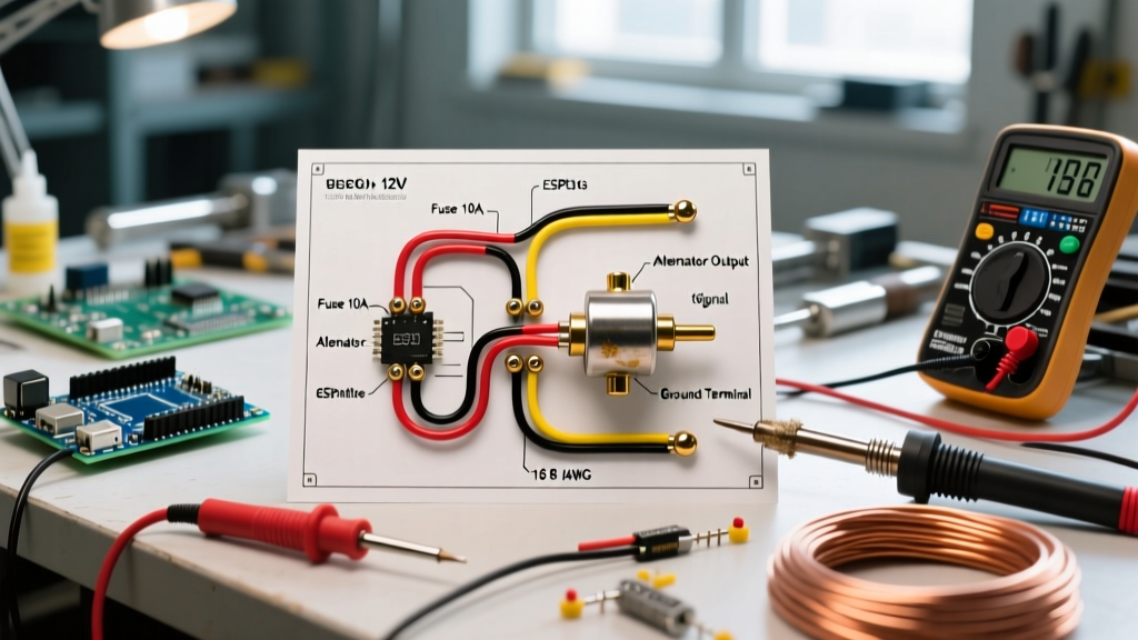
Many classic Ford and GM vehicles wired the electric choke to the alternator's stator (or 'R') terminal. This is widely considered the safest method for daily drivers.
- How it Works: The stator terminal outputs unrectified AC voltage (typically 7V to 9V AC) only when the alternator is spinning and producing current.
- Safety Advantage: If you leave the ignition key in the 'ON' position without the engine running (e.g., listening to the radio at a car show), the choke receives zero voltage. This prevents the bimetallic spring from overheating and burning out, and eliminates the risk of a dead battery.
- Compatibility Note: Modern one-wire alternators (like the Powermaster 17294) often omit the stator terminal. In these 2026 restomod builds, you must revert to Method A with a switched ignition relay.
SAE J1128 Compliance: Selecting the Correct Wire
The most frequent safety violation in home-built wiring harnesses is using standard PVC building wire (THHN/THWN) or cheap trailer wire in the engine bay. Engine bays routinely exceed 100°C (212°F) near the firewall and intake manifold.
According to SAE J1128 standards, automotive engine bay wiring must utilize cross-linked polyethylene (XLPE) insulation. As of 2026, high-temperature GXL and TXL wire remains highly accessible, costing approximately $0.35 to $0.55 per foot from specialty suppliers.
| Wire Type | Insulation Material | Max Temp Rating | Code Compliance | Use Case |
|---|---|---|---|---|
| GXL | Cross-linked (XLPE) | 125°C (257°F) | SAE J1128 | Standard engine bay routing |
| TXL | Cross-linked (XLPE) | 125°C (257°F) | SAE J1128 | Tight bends, modern harnesses |
| THHN | PVC / Nylon | 90°C (194°F) | NEC (Building) | NEVER use in engine bays |
| Primary | PVC | 85°C (185°F) | None | Interior cabin only |
Wire Gauge & Fusing Matrix
Selecting the correct American Wire Gauge (AWG) prevents voltage drop, which can cause the choke to open too slowly, leading to a rich condition, fouled spark plugs, and washed cylinders during cold starts. The following matrix assumes a standard 2.5 Amp choke draw.
| Wire Run Length (One Way) | Recommended AWG (Auto) | Recommended AWG (Marine ABYC) | Required Fuse Size |
|---|---|---|---|
| Under 5 Feet | 16 AWG | 14 AWG | 5A ATO |
| 5 to 10 Feet | 14 AWG | 12 AWG | 5A or 10A ATO |
| 10 to 15 Feet | 12 AWG | 10 AWG | 10A ATO |
Note: Marine applications require thicker wire (lower AWG number) due to ABYC E-11 voltage drop limitations and the corrosive environment that degrades copper stranding over time.
Critical Failure Modes & Troubleshooting
Even with a perfect wiring diagram, edge cases and legacy vehicle quirks can cause system failures. Here is how to diagnose the most common issues.
1. The 'Ignition Coil Positive' Mistake
A pervasive myth in old-school hot rodding is wiring the electric choke to the positive terminal of the ignition coil. Do not do this. Classic vehicles with points-style ignitions use a ballast resistor wire that drops the voltage at the coil positive to roughly 7V–9V while running. At 7V, the electric choke heating element will not generate enough heat to fully open the butterfly valve, resulting in a perpetually rich mixture and severe carbon buildup.
2. Voltage Drop at the Spade Terminal
The spade connector on Holley and Edelbrock choke caps is notorious for corroding or loosening due to engine vibration. A loose connection introduces resistance, dropping the voltage at the choke cap. Use a high-quality, heat-shrink-sealed female spade connector (such as the Pico 0562-PT series) and apply dielectric grease to prevent moisture ingress.
3. Bimetallic Spring Indexing
If the choke is receiving a verified 12.0V+ at the cap, but the butterfly remains closed after 3 minutes of idling, the internal bimetallic spring may be unindexed. Remove the three screws holding the cap, rotate the cap counter-clockwise until the butterfly just touches the high-idle cam, then rotate it clockwise 1/2 to 1 full turn (depending on ambient temperature) and tighten the screws.
Expert Safety Warning: Never test an electric choke by applying direct 12V from a battery charger while the carburetor is flooded or off the engine. The heating element can reach temperatures exceeding 150°C, and if fuel vapors are present in the choke horn, it can act as an ignition source. Always test continuity and resistance (typically 4 to 8 ohms cold) with a multimeter before applying live power.
Summary of Best Practices
To ensure your classic car or marine vessel passes tech inspection and remains safe on the road or water, always treat the electric choke wiring diagram as a critical safety circuit. Use SAE J1128 GXL wire, fuse within 18 inches of the power source, verify your ground path through the carburetor body, and avoid the ignition coil positive terminal. For modern EFI-converted vehicles retaining a carburetor for auxiliary systems, utilize a dedicated fused relay block to isolate the choke draw from sensitive ECU circuits. For further reading on automotive wire sizing and voltage drop calculations, consult the comprehensive guides at Mad Electrical.