
Understanding the Nakto Electric Bike Electrical Architecture
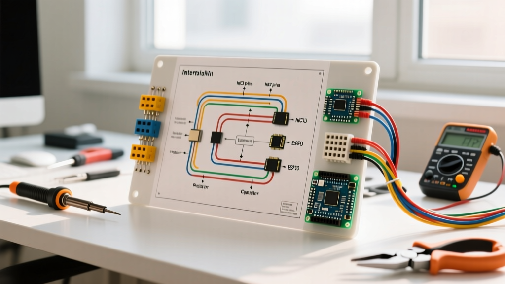
Nakto electric bikes, including popular models like the Pony, Cruiser, Stroll, and Cargo, rely on standardized 36V and 48V brushless DC (BLDC) hub motor systems. While Nakto provides excellent value, their generic wiring harnesses can be notoriously confusing for DIY repairmen and upgrade enthusiasts. A proper nakto electric bike wiring diagram is not just a luxury; it is an absolute necessity when diagnosing a dead motor, replacing a fried controller, or upgrading to a higher-capacity lithium-ion battery pack.
Unlike proprietary systems from brands like Bosch or Shimano, Nakto utilizes open-architecture components. This means the controller, motor, pedal assist system (PAS), and throttle are interconnected via industry-standard Julet (Higo) waterproof connectors or older screw-type SM connectors. Understanding the pinouts, wire gauges, and signal logic of these connections is the key to reviving a dead e-bike or safely boosting its performance in 2026.
Core Components in the Nakto Wiring Harness
Before diving into the schematic, you must identify the primary nodes in the Nakto electrical ecosystem. The wiring harness acts as the central nervous system, routing power and low-voltage signals between four main components:
- The Battery Pack: Typically a 36V (10S) or 48V (13S) lithium-ion pack outputting via an XT60 or XT90 discharge connector.
- The Motor Controller: The aluminum-boxed brain that converts DC battery power into 3-phase AC square or sine waves to drive the hub motor.
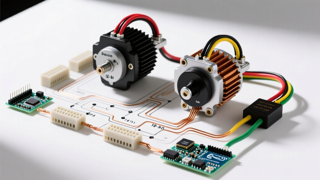
- The Rear Hub Motor: Usually a 350W or 500W direct-drive or geared BLDC motor containing three thick phase wires and five thin hall-sensor wires.
- Peripheral Inputs: The thumb throttle, Pedal Assist Sensor (PAS), brake motor-inhibitors, and the LCD display unit.
Nakto Electric Bike Wiring Diagram: Pinout & Connection Matrix
The most critical part of any motor wiring tutorial is understanding the color-coded pinouts. While generic Chinese controllers occasionally deviate, 95% of Nakto factory controllers follow the standard BLDC color matrix outlined below. Always verify with a multimeter before applying power.
| System / Function | Wire Colors | Gauge (AWG) | Connector Type | Voltage / Signal Type |
|---|---|---|---|---|
| Motor Phase (Power) | Yellow, Green, Blue (Thick) | 14 AWG - 12 AWG | 4.5mm Bullet / SM | High-Current 3-Phase AC |
| Motor Hall Sensors | Red, Black, Yellow, Green, Blue | 22 AWG | 5-Pin Julet / SM | 5V DC Logic (0-5V Pulse) |
| Battery Main Power | Red (+), Black (-) | 10 AWG - 8 AWG | XT60 / XT90 | 36V - 54.6V DC |
| Throttle Input | Red (5V), Black (GND), White/Green | 20 AWG | 3-Pin Julet | 0.8V to 4.2V Analog |
| Pedal Assist (PAS) | Red (5V), Black (GND), Yellow/White | 20 AWG | 3-Pin Julet | 5V Digital Pulse |
| Controller Self-Learn | Two White Wires (Single Pin) | 20 AWG | Single-Pin SM | Logic Trigger (Momentary) |
Step-by-Step Motor Wiring Tutorial
Whether you are replacing a burnt-out controller or rewiring a salvaged Nakto hub motor, follow this precise sequence to avoid shorting the MOSFETs or damaging the hall sensors.
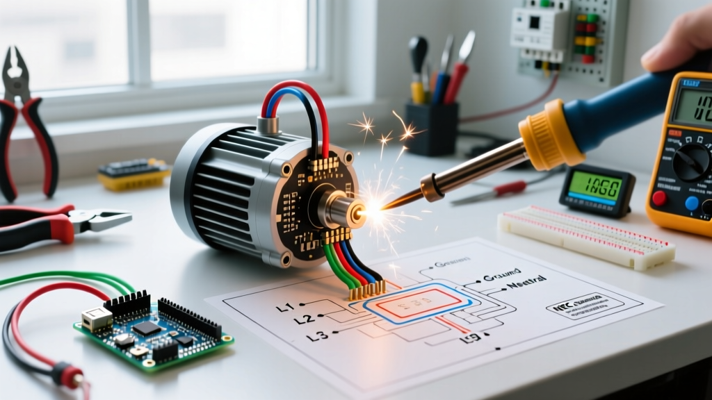
Step 1: High-Current Phase Wire Termination
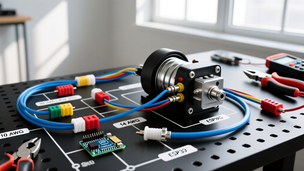
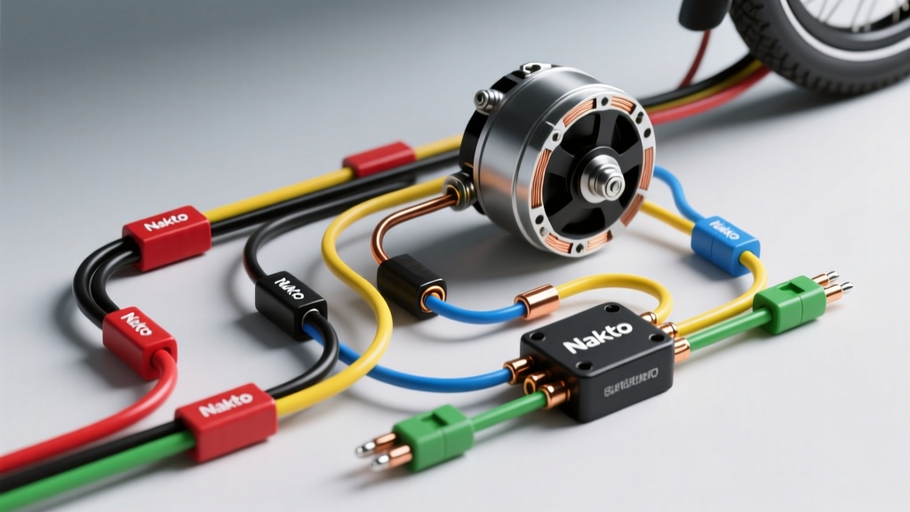
The phase wires (Yellow, Green, Blue) carry the raw amperage (up to 22A continuous, 30A peak on a 500W Nakto motor). Never use solder alone for these connections; the heat from the motor will melt the solder joint over time. Crimp 4.5mm gold-plated bullet connectors using a heavy-duty hex crimper, then seal the joint with dual-wall marine-grade heat shrink tubing. Match the colors exactly: Yellow to Yellow, Green to Green, Blue to Blue. Swapping these will cause the motor to stutter violently and can instantly blow the controller's power MOSFETs.
Step 2: Hall Sensor Calibration & Connection
The 5-pin hall sensor connector provides the controller with real-time rotor position data. The Red wire supplies 5V, Black is ground, and the remaining three are signal wires. Critical Warning: Never apply 12V or battery voltage to the hall sensor pins. Doing so will instantly fry the internal sensors inside the motor stator, requiring a complete motor teardown to replace.
Step 3: Utilizing the 'Self-Learn' Wire Loop
If you are installing an aftermarket replacement controller on a Nakto bike, the phase and hall color combinations might not perfectly align with the motor's internal timing. This is where the two white 'Self-Learn' wires come in. Connect the two white wires together while the motor is elevated off the ground. The controller will automatically cycle through all 36 possible phase/hall combinations. Once the motor spins smoothly in the correct forward direction, disconnect the white wires to lock in the timing.
Common Wiring Failures & Diagnostic Fixes
When troubleshooting a Nakto e-bike, visual inspection and multimeter testing are your best tools. Here are the most frequent failure modes specific to this platform:
- Melted Phase Connectors: The stock plastic SM connectors used on older Nakto models are prone to high resistance. If water enters or the connection loosens, arcing occurs, melting the plastic. Fix: Cut off the melted connectors and solder/heat-shrink 4.5mm bullet connectors directly.
- Erratic Motor Stuttering (Cogging): This usually indicates a failed hall sensor or a broken 22 AWG signal wire inside the motor cable. Test: Set your multimeter to DC Volts. Back-probe the hall signal wires while slowly spinning the wheel by hand. You should see the voltage cleanly alternate between 0V and 5V. A reading stuck at 2.5V or 0V indicates a dead sensor.
- XT60 Anti-Spark Failure: Plugging in a 48V Nakto battery without an anti-spark resistor can cause a massive inrush current that welds the XT60 contacts together or damages the controller's input capacitors. Always use an XT90-S (anti-spark) connector for 48V systems.
Pro-Tip for 2026 Upgrades: If you are pushing your Nakto hub motor beyond its stock 350W rating (e.g., via controller shunt mods), upgrade the battery-to-controller wiring from 10 AWG to 8 AWG silicone wire. The voltage sag on thin wires at 25+ Amps will prematurely trigger the battery's BMS low-voltage cutoff.
Essential Tools for E-Bike Wiring
To execute these repairs safely and reliably, you need the right bench equipment. Skip the cheap automotive crimpers and invest in proper e-bike tooling:
- Temperature-Controlled Soldering Station: A 60W+ station (like the Hakko FX888D) is required to properly flow solder onto thick 10 AWG battery leads without cold joints.
- Digital Multimeter: Essential for testing 5V hall logic and checking for continuity/shorts before applying main battery power.
- Wire Strippers & Hex Crimpers: Specifically designed for 4.5mm and 5.5mm bullet connectors to ensure a gas-tight mechanical crimp.
- Dielectric Grease: Apply a small dab to all exterior Julet connectors to prevent galvanic corrosion and water ingress, a common killer of Nakto PAS sensors.
Authoritative References & Further Reading
For official schematics and deeper technical standards, consult the following resources:
- Nakto Official User Manuals - Provides baseline warranty specs, stock controller amp limits, and official error code definitions for factory LCD displays.
- Grin Technologies E-Bike Tech Center - The industry gold standard for BLDC motor phase angles, hall sensor logic, and advanced controller programming tutorials.
- American Wire Gauge (AWG) Standards - Use this reference to calculate voltage drop and current-carrying capacity when upgrading your Nakto battery discharge leads.
Mastering the nakto electric bike wiring diagram transforms you from a passive rider into a capable e-bike mechanic. By respecting the color codes, upgrading sub-par connectors, and properly utilizing the self-learn calibration, you can ensure your Nakto hub motor runs efficiently and reliably for thousands of miles.