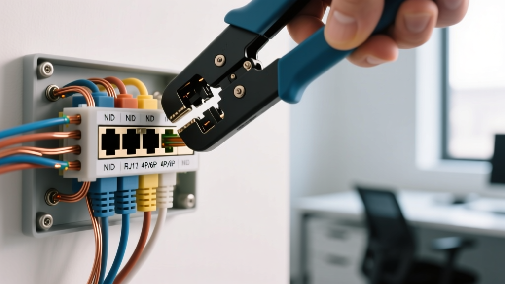

Bridging the Telecom Panel and Interior RJ11 Jacks
Even in 2026, with the widespread adoption of VoIP and fiber-optic internet, hardwired telephone infrastructure remains a critical backbone for residential security panels, medical alert systems, and fail-safe communications. For electrical professionals and advanced DIYers, understanding the wiring diagram for phone jack installations requires looking beyond the wall plate. A reliable telecom circuit begins at the main service panel's Network Interface Device (NID) and relies on strict adherence to structured wiring principles and National Electrical Code (NEC) grounding standards.
This guide approaches phone jack wiring from a Panel & Breaker perspective, detailing how to properly terminate cables at the NID, map Cat5e/Cat6 to RJ11 6-position jacks, and bond the telecom ground to your main electrical service panel to prevent dangerous potential differences.
The Telecom Panel: Understanding the NID Demarcation Point
Before pulling wire to interior jacks, you must understand the demarcation point. The FCC mandates that the telephone company's responsibility ends at the Network Interface Device (NID), typically a gray or beige box mounted on the exterior wall near the main electrical service panel. Inside the NID, there is a clear division between the 'Telco Side' (sealed) and the 'Customer Side' (accessible).
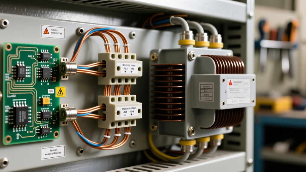
Modern structured wiring enclosures, such as the Leviton 47689-A Telecom Distribution Module, often serve as the interior hub immediately following the NID. When planning your wiring diagram, you are essentially mapping the path from the NID's customer-side 110 IDC (Insulation Displacement Contact) blocks, through the interior panel, to the individual RJ11 wall jacks.
Expert Insight: Never splice telecom wires using wire nuts inside the NID. Splices introduce impedance mismatches that degrade DSL/VDSL sync rates and cause voltage drops on POTS (Plain Old Telephone Service) lines. Always use a continuous run of 24 AWG solid copper Cat5e or Cat6 from the NID to the interior jack.
Standard Wiring Diagram for Phone Jack (RJ11 6-Position)
The standard residential phone jack uses an RJ11 connector. While the physical jack has 6 positions (6P), it typically uses either 2 or 4 conductors (6P2C or 6P4C). When wiring from a modern Cat5e or Cat6 cable, you must map the twisted pairs to the correct RJ11 pins to maintain polarity and minimize crosstalk.
RJ11 Pinout and Cat5e/6 Color Code Mapping
| RJ11 Pin | Standard 4-Core Quad Color | Cat5e / Cat6 Mapping (T568A/B) | Function / Line Assignment |
|---|---|---|---|
| Pin 1 | Unused | White/Green (Pair 3) | Line 3 Tip (Rarely used) |
| Pin 2 | Black | White/Orange (Pair 2) | Line 2 Tip (Ring Voltage) |
| Pin 3 | Green | Blue (Pair 1) | Line 1 Tip (Positive DC) |
| Pin 4 | Red | White/Blue (Pair 1) | Line 1 Ring (Negative DC) |
| Pin 5 | Yellow | Orange (Pair 2) | Line 2 Ring (Ring Voltage) |
| Pin 6 | Unused | Green (Pair 3) | Line 3 Ring (Rarely used) |
Critical Note on Polarity: Line 1 (Pins 3 and 4) carries the primary dial tone. The Green wire (Tip) is positive relative to the Red wire (Ring). While analog phones are generally polarity-insensitive, modern security dialers, VoIP Analog Telephone Adapters (ATAs), and DSL modems require strict Tip-to-Tip and Ring-to-Ring polarity to function correctly and pass FCC Part 68 compliance tests.
Step-by-Step NID to RJ11 Panel Wiring Flow
Executing the wiring diagram for phone jack circuits requires precision at the termination points. Follow this sequence to ensure a clean, noise-free circuit.
- Prepare the Cable: Strip back 2 inches of the Cat5e/Cat6 jacket. Untwist the Blue/White-Blue pair (Line 1) and Orange/White-Orange pair (Line 2) no more than 0.5 inches to maintain the twist rate and prevent near-end crosstalk (NEXT).
- Terminate at the NID: Using a 110-blade punch-down tool (e.g., Klein Tools 110 IDC), punch the Blue wire to the 'Tip' terminal and White/Blue to the 'Ring' terminal on the NID's customer-side block. Ensure the cutting blade faces outward to trim the excess wire cleanly.
- Route Through the Panel: Run the cable through the interior structured wiring panel. Avoid running telecom cables parallel to 120V/240V AC branch circuits. The NEC requires a minimum 2-inch separation between communications cables and AC power cables to prevent electromagnetic interference (EMI).
- Punch Down at the Wall Jack: At the RJ11 keystone or surface-mount jack, punch down the Blue wire to Pin 3, White/Blue to Pin 4, Orange to Pin 5, and White/Orange to Pin 2. Leave Pins 1 and 6 empty for standard 2-line residential setups.
NEC Article 800: Grounding and the Main Electrical Panel
The most frequently overlooked aspect of telecom wiring is the grounding electrode conductor (GEC). From a Panel & Breaker perspective, the telecom ground is not optional; it is a life-safety requirement designed to prevent lightning strikes or accidental power line contact from energizing the phone lines and causing a fire or electrocution hazard.
According to NFPA 70 (NEC) Article 800.100, the primary protector at the NID must be grounded using a minimum 14 AWG bare copper wire. However, if the grounding conductor exceeds 20 feet in length, you must upgrade to 12 AWG or 10 AWG copper.
Bonding to the Electrical Service Panel
- Locate the Ground Bar: Identify the main equipment grounding bar inside your primary electrical service panel (e.g., Square D HOM4080M150PC or Eaton BR Main Breaker Panel).
- Make the Connection: The telecom grounding conductor must terminate on the same ground bar as the AC service ground. If the NID is on the opposite side of the wall from the main panel, use an Intersystem Bonding Termination (IBT) bar, which is now required by modern NEC codes to provide a centralized, accessible grounding point for telecom, cable, and satellite without opening the main electrical panel cover.
- Verify Bonding: Use a multimeter to verify continuity between the NID's grounding block and the main panel's ground bar. Resistance should read less than 0.5 ohms.
Troubleshooting Common NID and Jack Failures
When a wired phone jack fails to deliver a dial tone or exhibits heavy static, the issue usually stems from improper termination or panel-level interference. Use the following diagnostic framework:
1. Voltage Testing at the NID
Disconnect the interior wiring at the NID test jack. Using a digital multimeter set to DC Volts, measure across the Tip and Ring terminals. A healthy POTS line from the telco will read between -44V and -52V DC. If you read 0V, the issue is on the telco side. If you read normal voltage at the NID but 0V at the interior RJ11 jack, you have an open circuit or a mis-punch on your 110 blocks.
2. Ring Voltage Verification
Set your multimeter to AC Volts and have a helper call the line. The ringing voltage is typically 90V AC at 20Hz superimposed on the DC talk battery. If the voltage is significantly lower (e.g., 40V AC), you likely have a short circuit or moisture ingress in the exterior cable jacket.
3. Identifying AC Hum and EMI
If the phone line has a persistent 60Hz hum, the telecom cable is likely running too close to a high-current breaker circuit (like a dryer or HVAC compressor) inside the wall cavity. Reroute the cable or install a ferrite choke near the RJ11 jack to suppress high-frequency noise.
Frequently Asked Questions (FAQ)
Can I use Cat6 cable for standard RJ11 phone jacks?
Yes, and it is highly recommended. While Cat6 is designed for gigabit Ethernet, its 23 AWG solid copper conductors and tighter twist rates provide superior protection against crosstalk and EMI compared to legacy 22 AWG quad phone wire. Simply map the Blue and Orange pairs to the RJ11 pins as outlined in the diagram above.
How do I wire a VoIP ATA (like an Ooma or Grandstream) to my existing wall jacks?
To distribute VoIP throughout the house, you must disconnect the exterior NID line to prevent back-feeding voltage into the telco grid. Then, plug your VoIP ATA's 'Phone' port into an RJ11 jack that connects directly to your interior structured wiring panel's 110 distribution block. Ensure the ATA supports the REN (Ringer Equivalence Number) load of all connected analog devices.
What is the FCC Part 68 requirement for phone jack wiring?
FCC Part 68 governs the direct electrical connection of customer premises equipment to the telephone network. It mandates the use of registered modular jacks (like the RJ11) and requires primary surge protection at the demarcation point to protect the public telecom grid from customer-side electrical faults.