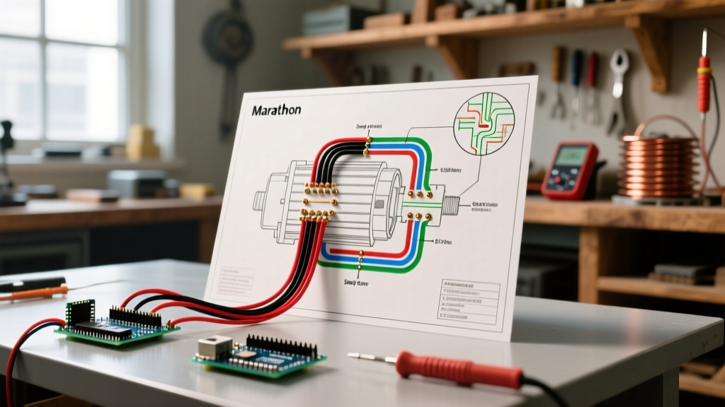

Decoding the Marathon Nameplate and Peckerhead Diagrams
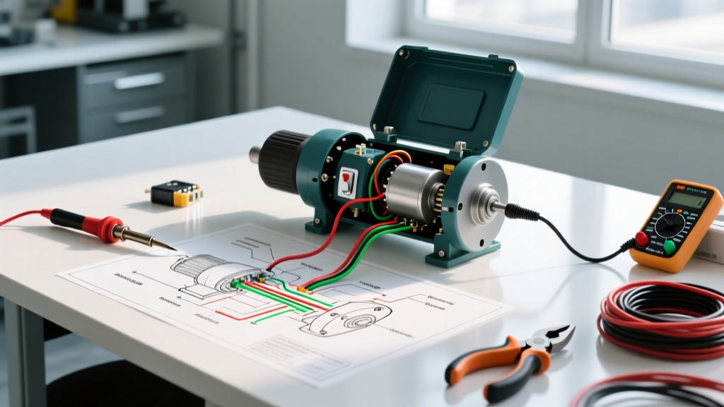
Marathon Electric, now a flagship brand under the Regal Rexnord portfolio, manufactures some of the most widely deployed NEMA and IEC frame motors in North America. Whether you are working with a standard D56 frame general-purpose motor, a C215T pump motor, or a heavy-duty inverter-rated Black Max unit, the wiring diagram located on the nameplate and inside the peckerhead (connection box) is your primary diagnostic map. Troubleshooting motor failures without referencing the specific Marathon electric motors wiring diagram for your exact model often leads to miswired coils, blown fuses, or catastrophic winding burnouts.
In 2026, with the widespread integration of smart motor protection relays and variable frequency drives (VFDs), understanding the foundational hardwired connections remains critical. A VFD cannot compensate for an incorrectly configured Wye/Delta peckerhead connection. This guide provides a deep-dive technical framework for using Marathon wiring schematics to isolate starting failures, thermal trips, and phase imbalances.
Anatomy of a Marathon Motor Connection Diagram
Before grabbing a multimeter, you must identify the specific diagram number stamped on the Marathon nameplate. Marathon typically uses standardized NEMA connection diagrams. For example, Diagram 10408 is frequently used for 9-lead dual-voltage three-phase motors, while Diagram 10304 is common for single-phase capacitor-start models. According to the NEMA MG 1 Standards, these diagrams dictate not just the line leads (T1 through T9), but also the internal thermal protector leads (usually labeled P1 and P2) and auxiliary cooling blower connections.
Locating and Verifying the Leads
Open the peckerhead cover. You will find numbered, color-coded, or lettered wires. On older Marathon motors, leads may be marked with tape or stamped ferrules. On newer Regal Rexnord production runs, laser-etched shrink tubing is standard. If the diagram calls for a high-voltage (460V) Wye connection, but you find T4, T5, and T6 isolated and capped while T1-T9 are bundled, the motor is miswired for low voltage, which will cause immediate magnetic saturation, excessive current draw, and thermal overload tripping if connected to a 480V supply.
9-Lead Three-Phase Dual Voltage Troubleshooting
The most common three-phase Marathon motors in industrial settings are 9-lead dual-voltage (230/460V) units. Troubleshooting these requires understanding whether the internal windings are configured in Wye (Star) or Delta. Most Marathon 9-lead motors in the C-face and D-frame ranges are Wye-connected internally.
Standard 9-Lead Wye Connection Matrix
| Voltage Setting | Line Connections (L1, L2, L3) | Internal Ties / Splices | Common Failure Symptom if Miswired |
|---|---|---|---|
| Low (230V) | L1: T1,T7 | L2: T2,T8 | L3: T3,T9 | T4-T5-T6 tied together | Motor runs hot, draws 2x FLA, trips breaker instantly. |
| High (460V) | L1: T1 | L2: T2 | L3: T3 | T4-T7, T5-T8, T6-T9 tied in pairs | Motor hums, fails to start, or runs at 1/3 speed with severe vibration. |
Troubleshooting Tip: If a 460V Marathon motor hums loudly and draws locked-rotor current but refuses to turn, check the high-voltage splice pairs. If T4, T5, and T6 are tied together (a low-voltage Wye configuration) while the supply is 460V, the windings are subjected to massive over-fluxing. Use a Fluke 87V industrial multimeter to verify continuity between the tied pairs before re-energizing.
Single-Phase Capacitor-Start Failures (Hawkeye & General Purpose)
Marathon's single-phase lineup, including the popular Hawkeye series, relies on a centrifugal switch and a start capacitor to generate the necessary phase shift for starting torque. The wiring diagram for these motors typically shows the main run winding, the start winding, the capacitor, and the switch in a specific series-parallel arrangement.
Step-by-Step Diagnostic Flow for Single-Phase No-Start Conditions
- Verify Line Voltage: Measure L1 to L2 at the motor terminal block. A reading below 198V (for a 230V nominal motor) indicates severe voltage drop in the branch circuit, preventing the centrifugal switch from disengaging.
- Test the Start Capacitor: Disconnect power and discharge the capacitor with a 20k-ohm, 5W bleeder resistor. Use a multimeter with capacitance testing. A Marathon 1 HP motor typically requires a 108-130 µF start capacitor. If the reading is below 95 µF, the capacitor is degraded and cannot provide the phase shift needed to start the rotor.
- Centrifugal Switch Continuity: With the motor at rest, the switch must be closed. Place your multimeter probes on the switch leads indicated on the Marathon diagram. You should read near 0.0 ohms. If the reading is infinite (OL), the switch contacts are pitted or the spring mechanism is seized, preventing the start winding from energizing.
Diagnosing Inverter-Duty (Black Max) Blower and Encoder Wiring
Marathon's Black Max inverter-duty motors are engineered to handle the high dv/dt voltage spikes and corona discharge associated with VFD output. However, these motors often feature independent cooling blowers and shaft encoders that require separate, low-voltage wiring. The diagram for a Black Max motor will separate the main power leads (U, V, W) from the auxiliary terminal box.
Critical Warning: Never wire the independent cooling blower of a Black Max motor to the VFD output. The blower must be wired to a constant line-voltage source or a dedicated VFD output programmed for constant speed. Running the blower off the main VFD output will cause the motor to overheat and fail when the drive is commanded to run at low frequencies (below 20 Hz).
When troubleshooting encoder feedback loss (e.g., the VFD throwing an F0004 Speed Feedback Error), consult the encoder pinout on the Marathon diagram. Verify the 5V DC or 24V DC excitation voltage at the encoder plug, and check the A, B, and Z channel shielded cables for continuity. Ensure the shield is grounded at the drive end only to prevent ground loops.
Multimeter Testing Matrix for Winding Faults
When the wiring diagram confirms the external connections are correct, but the motor still trips the overload relay, you must test the windings themselves. Refer to the NFPA 70 (National Electrical Code) Article 430 for proper motor overload sizing and protection guidelines before conducting these tests.
| Test Type | Multimeter Setting | Expected Reading (Healthy Marathon Motor) | Failure Indication |
|---|---|---|---|
| Winding Continuity | Resistance (Ohms) - Low Range | 0.5 to 5.0 ohms (varies by HP and frame) | OL (Open circuit) indicates a blown internal winding or severed lead. |
| Phase Balance (3-Phase) | Resistance (Ohms) | Within 2% resistance across all three phases | >5% variance indicates shorted turns between coils. |
| Ground Fault (Megger) | Insulation Tester (500V DC) | >10 Megohms to ground (frame) | <2 Megohms indicates insulation breakdown, moisture ingress, or winding-to-frame short. |
| Thermostat (P1-P2) | Continuity / Diode | 0.0 ohms (Closed circuit when motor is cold) | OL (Open) indicates tripped thermal protector or broken P-lead wire. |
Thermal Protection (Thermostat/Thermistor) Integration
Many Marathon motors, especially those designated as 'Thermally Protected' (TP) on the nameplate, feature internal bi-metallic thermostats or PTC thermistors embedded directly in the stator end-turns. The wiring diagram will show these as P1 and P2 (or sometimes T1 and T2 for thermistors).
Troubleshooting the Thermal Circuit: If the motor refuses to start and the external control circuit relies on the internal thermostat for the control logic, measure across P1 and P2. If the motor is cold and you read an open circuit, the internal thermostat has failed open, or the thin gauge P-lead wires have broken inside the peckerhead conduit. Do not attempt to bypass the P1/P2 leads permanently; doing so violates UL listings and NEC safety requirements, risking a stator fire in the event of a mechanical stall.
Final Verification and Safety Protocols
Always lock out and tag out (LOTO) the main disconnect before altering any peckerhead connections. After reconfiguring the motor based on the Marathon electric motors wiring diagram, perform a 'bump' test. Energize the motor for less than one second to verify the direction of rotation and ensure there is no immediate mechanical binding or electrical arcing. For three-phase motors running backward, simply swap any two line leads (e.g., L1 and L3) at the terminal block—never swap internal T-leads, as this will unbalance the magnetic fields and cause severe vibration.
By systematically cross-referencing the physical wiring against the manufacturer's schematic and utilizing targeted multimeter diagnostics, you can accurately isolate 95% of all Marathon motor electrical failures without resorting to unnecessary component replacement.