
Integrating the Rotary Phase Converter into Your Electrical Panel
Upgrading a residential or light-commercial workshop to handle 3-phase machinery requires more than just plugging in an idler motor. A properly engineered panel integration ensures balanced voltage, reliable motor starting, and strict adherence to safety codes. In 2026, with copper prices remaining volatile and modern CNC machines demanding cleaner power, understanding the exact wiring diagram for rotary phase converter systems is critical for both efficiency and safety.
Unlike static converters or variable frequency drives (VFDs), a rotary phase converter (RPC) generates a true, usable 3-phase sine wave that can power an entire subpanel of equipment simultaneously. However, this capability introduces complex panel-level challenges: sizing the main input breaker correctly, managing the high-leg (wild leg) routing, and balancing the capacitive loads. This guide breaks down the exact panel and breaker architecture required for a safe, code-compliant RPC installation.
Core Anatomy of an RPC Control Panel
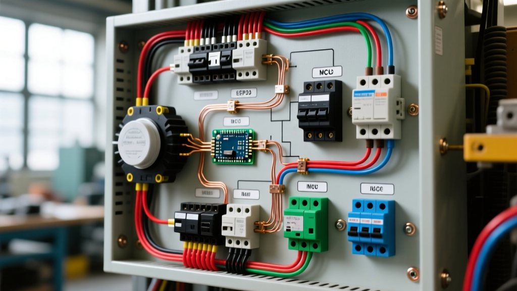
Before tracing the wiring diagram, you must understand the internal architecture of the RPC control enclosure. Whether you are using a legacy American Rotary AR-series or a modern Phase-A-Perfect (PAP) digital unit, the internal panel components serve distinct functions:
- Input Lugs (L1 & L2): Accept the single-phase 240V utility feed.
- Potential Relay & Start Capacitors: Provide the initial phase shift and torque required to spin the idler motor up to synchronous speed (typically 1,800 or 3,600 RPM).
- Run Capacitor Bank: Stays in the circuit continuously to balance the voltage between the generated leg (T3) and the input legs (L1/L2).
- Output Busbar (L1, L2, T3): Distributes the manufactured 3-phase power to the load subpanel.
NEC Code Mandate: Under NFPA 70 (National Electrical Code) Article 455, phase converters must be treated as specific utilization equipment. Article 455.7 dictates that the single-phase input overcurrent protection must be sized based on the RPC manufacturer's exact specifications, which often exceed the standard 125% continuous load rule due to the massive inrush current required to start the idler motor.
Step-by-Step Panel Wiring Diagram Flow
When drafting your physical wiring diagram for the shop, the power flow must follow a strict sequence to ensure selective coordination and safe disconnects. Here is the standard routing for a 10 HP to 20 HP RPC system:
1. Utility Feed to Main Disconnect
Your single-phase utility feed (e.g., 240V split-phase) enters the main service disconnect. From here, a dedicated feeder runs to the RPC's primary overcurrent protection device. Do not share this feeder with general lighting or 120V receptacle circuits.
2. Input Breaker to RPC Enclosure
The feeder lands on a 2-pole breaker sized specifically for the RPC's starting surge. For a 10 HP RPC, this is typically a 100A breaker. The load side of this breaker feeds directly into the L1 and L2 input lugs of the RPC control panel.
3. The Idler Motor Connection
Inside the RPC panel, L1 and L2 pass through the main contactor and connect to the idler motor's T1 and T2 terminals. The control panel's internal circuitry generates the T3 (wild leg) voltage, which is routed to the motor's T3 terminal to complete the 3-phase delta configuration.
4. Output to the 3-Phase Subpanel
The output busbar of the RPC (L1, L2, and T3) feeds a dedicated 3-phase subpanel. Critical Rule: The T3 generated leg must never be routed through a standard single-pole breaker for 120V control circuits. It must only feed 3-phase loads or 240V 3-phase equipment.
Breaker Sizing and Wire Gauge Matrix (2026 Standards)
Sizing the wire and breaker for the single-phase input side is where most DIY installations fail. The idler motor requires significant amperage to start, meaning the input breaker must handle the inrush without nuisance tripping, while the wire must handle the continuous thermal load. With 2026 copper costs driving many installers toward aluminum feeders, the following matrix includes both THHN Copper and XHHW-2 Aluminum options.
| RPC Size (HP) | Max Input Amps | Main Breaker Size | Copper Wire (THHN) | Aluminum Wire (XHHW-2) |
|---|---|---|---|---|
| 5 HP | 28A | 60A (2-Pole) | 6 AWG | 4 AWG |
| 7.5 HP | 42A | 90A (2-Pole) | 4 AWG | 2 AWG |
| 10 HP | 54A | 100A (2-Pole) | 3 AWG | 1 AWG |
| 15 HP | 80A | 150A (2-Pole) | 1/0 AWG | 3/0 AWG |
| 20 HP | 108A | 200A (2-Pole) | 2/0 AWG | 4/0 AWG |
Note: Always verify the specific nameplate data on your RPC. Digital units from manufacturers like Phase-A-Perfect often feature soft-start circuitry that may allow for slightly smaller input breakers compared to legacy potential-relay systems.
The 'Wild Leg' (T3) Protocol and Subpanel Routing
The most dangerous aspect of an RPC wiring diagram is the mismanagement of the generated leg, universally known as the 'wild leg', 'high leg', or 'stinger'. In a 240V delta system, the voltage from L1 to Neutral is 120V, and L2 to Neutral is 120V. However, T3 to Neutral measures approximately 208V.
If a 120V single-phase circuit (like a machine's control transformer or a standard outlet) is accidentally tied to the T3 bus, the 208V will instantly destroy the 120V components and create a severe fire hazard.
Panel Routing Rules for T3:
- Identification: Per NEC 110.15 and 250.97, the T3 wild leg must be durably marked. In modern installations, this means using orange THHN wire or wrapping the wire in high-visibility orange electrical tape at every termination point.
- Busbar Placement: When landing the 3-phase output into a standard 3-phase panelboard, the T3 wild leg must be terminated on the 'B' phase (the center phase in most North American panelboards). This physical separation prevents standard single-pole 120V breakers from accidentally clipping onto the high leg.
- Control Circuit Isolation: If your 3-phase CNC machine requires 120V for its internal computer, you must step down the voltage using a 240V-to-120V isolation transformer fed by L1 and L2, entirely bypassing the T3 leg for control power.
Voltage Balancing: Tuning the Run Capacitors
A wiring diagram is only half the battle; the electrical tuning of the panel ensures the machinery survives. When the idler motor is spinning under no-load conditions, the voltage between L1-T3 and L2-T3 will often be unbalanced. The NEMA MG 1 standard recommends that voltage unbalance should not exceed 1% for optimal motor life, though a 2-3% unbalance is generally acceptable in workshop environments.
To achieve this, the RPC panel utilizes a run capacitor bank. The general rule of thumb for tuning is adding 10 to 15 microfarads (µF) of run capacitance per horsepower of the idler motor. These capacitors are wired in parallel between L1-T3 and L2-T3. Using a true-RMS multimeter, measure the voltages while the RPC is idling. If T3-L1 is reading 250V and T3-L2 is reading 225V, you must shift capacitance from the L1-T3 bank to the L2-T3 bank to balance the generated sine wave.
Common Failure Modes and Panel Troubleshooting
Even with a perfect wiring diagram, RPC panels experience specific failure modes over time. Recognizing these edge cases will save you hours of diagnostic downtime:
- Potential Relay Sticking: In legacy RPCs, the potential relay is responsible for disconnecting the start capacitors once the idler reaches speed. If the relay contacts weld shut, the start capacitors remain in the circuit, overheat, and violently vent (pop). Fix: Upgrade to a digital solid-state start module.
- Single-Phasing the Load: If a breaker on the single-phase input side trips, or a lug burns off L1/L2, the idler motor will continue to spin via inertia and backfeed a degraded, low-voltage 3-phase signal to your subpanel. This will burn out the windings on your expensive 3-phase loads. Fix: Install a 3-phase voltage monitoring relay in the RPC output subpanel that drops out the main contactor if phase loss or severe unbalance is detected.
- Capacitor Degradation: Metallized film run capacitors lose their microfarad rating over years of thermal cycling. If your RPC suddenly struggles to start heavy loads or the wild leg voltage drops below 220V, test the run capacitors with a digital capacitance meter and replace any that have drifted more than 5% from their rated value.
Final Safety and Grounding Considerations
Never use the RPC's generated T3 leg as a grounding reference. The equipment grounding conductor (EGC) must be routed from the main single-phase service panel directly to the 3-phase subpanel and all machinery enclosures. The RPC idler motor frame must also be bonded to this EGC. By strictly following this panel wiring diagram for rotary phase converter setups, you ensure that your 3-phase equipment receives clean, balanced power while maintaining the highest standards of electrical safety in your facility.