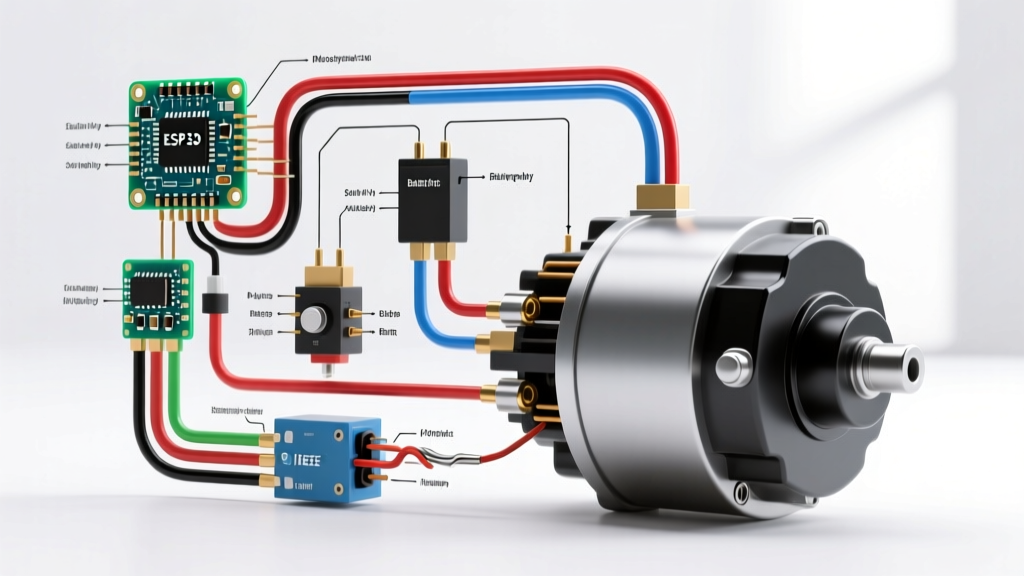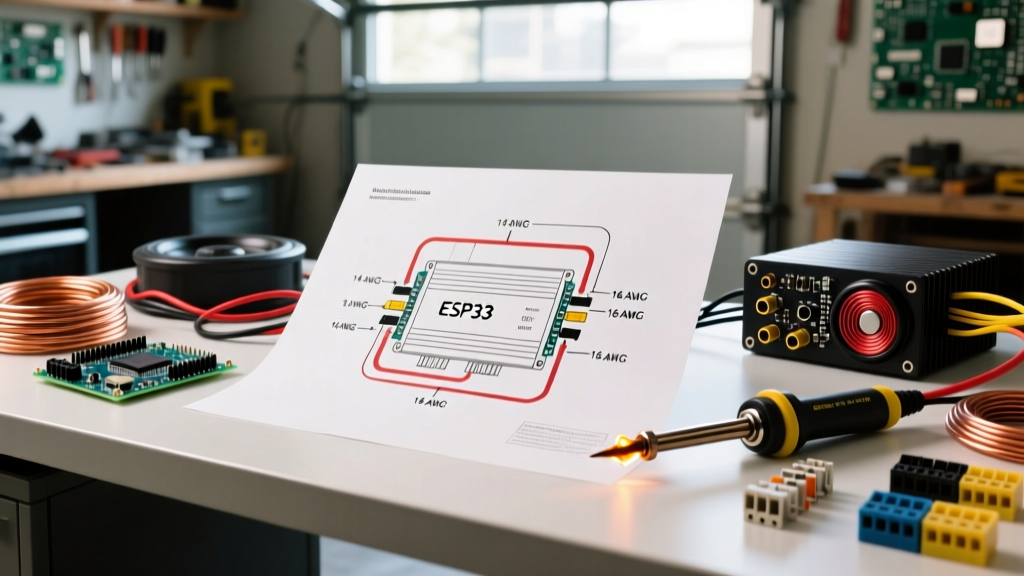

The Anatomy of a Professional Wiring Diagram for Car Amplifier Systems
Installing an aftermarket audio system requires more than just connecting red to positive and black to negative. A precise wiring diagram for car amplifier setups is the blueprint for achieving clean, distortion-free sound while protecting your vehicle's electrical system from catastrophic failure. Whether you are powering a pair of door speakers or a 1500-watt subwoofer enclosure, understanding the flow of current from the alternator to the voice coils is critical.
In this vehicle-specific guide, we break down the exact wiring topology required for modern Class-D and Class-AB amplifiers. We will cover wire gauge mathematics, chassis grounding protocols, and signal routing techniques to eliminate alternator whine and ground loops. As of 2026, with the rise of high-resolution DSP (Digital Signal Processing) amplifiers like the JL Audio VX800/8i (retailing around $799) and the Rockford Fosgate Punch P500X2 ($249), clean power delivery is more important than ever to prevent digital clipping and processor rebooting.
Wire Gauge Selection Matrix: AWG vs. Amperage
The most common failure point in car audio is undersized power wire. According to SAE International technical standards (specifically SAE J1128 for automotive low-tension cable), copper-clad aluminum (CCA) wire has up to 40% higher resistance than pure oxygen-free copper (OFC). Always use OFC wire for your main power runs. Below is the definitive matrix for selecting the correct American Wire Gauge (AWG) based on your amplifier's total RMS wattage and the distance from the battery.
| Total RMS Wattage | Max Current Draw (14.4V) | Recommended OFC Wire Gauge (Under 16 ft) | Recommended OFC Wire Gauge (Over 16 ft) | Required Inline Fuse |
|---|---|---|---|---|
| Up to 250W | ~25 Amps | 8 AWG | 4 AWG | 30A AGU / Mini-ANL |
| 250W - 500W | ~50 Amps | 4 AWG | 4 AWG | 60A ANL |
| 500W - 1000W | ~85 Amps | 4 AWG | 2 AWG | 100A ANL |
| 1000W - 1500W | ~130 Amps | 1/0 AWG | 1/0 AWG | 150A ANL / Class T |
| 1500W - 3000W+ | 200+ Amps | Multiple runs of 1/0 AWG | Multiple runs of 1/0 AWG | Class T Fuse (250A+) |
Note: Current draw is calculated assuming a realistic 50% efficiency for Class-AB amps and 75% efficiency for Class-D amps. Always size your inline fuse based on the wire's ampacity limit, not just the amplifier's onboard fuses.
Step-by-Step Installation Flow
Follow this sequential routing protocol to ensure safety and signal integrity. For comprehensive visual references, Crutchfield's comprehensive car audio learning center provides excellent vehicle-specific dash disassembly guides to complement this electrical topology.
1. The Power Circuit (Battery to Firewall)
Disconnect the negative battery terminal before beginning. Route your main OFC power wire from the positive battery terminal to the amplifier location. You must install an inline fuse holder within 18 inches of the battery positive terminal. This is a non-negotiable safety requirement; if a short occurs between the firewall and the battery, an unfused wire can melt through the chassis and start an electrical fire. Use a rubber grommet when passing through the factory firewall to prevent the chassis metal from slicing through the wire insulation.
2. The Critical Ground Connection
The ground wire completes the circuit and is the number one cause of audio system noise. Keep the ground wire as short as possible—ideally under 18 inches.
- Preparation: Use 80-grit sandpaper to remove all factory paint, primer, and clear coat from the chassis bolt location until you see bare, shiny metal.
- Hardware: Use a factory-threaded bolt or a self-tapping stainless steel screw. Avoid using seatbelt bolts, as they often feature thread-locking compound that acts as an insulator.
- Protection: Coat the sanded area with dielectric grease or clear nail polish after tightening to prevent rust and oxidation, which will increase resistance over time.
3. Remote Turn-On and Signal Routing
The remote turn-on lead (typically an 18 AWG blue/white wire) signals the amplifier to power on when the head unit is active. Connect this to the head unit's 'Amp Turn-On' or 'Power Antenna' output.
Pro-Tip for DSP Amps: Modern DSP amplifiers draw more current on the remote circuit. If your head unit's remote output exceeds 300mA, use a 12V automotive relay triggered by the head unit to switch the main 12V power to the amp's remote terminal.Route your RCA signal cables and speaker wires down the opposite side of the vehicle from your main power wire. Running high-current power wires parallel to low-voltage RCA cables induces electromagnetic interference (EMI), resulting in a high-pitched alternator whine that scales with engine RPM.
High-Draw Systems: The 'Big Three' Upgrade
If your system draws over 1500 watts RMS, a standard wiring diagram for car amplifier setups is insufficient. You must upgrade the vehicle's baseline electrical infrastructure. Known in the industry as the 'Big Three' upgrade, this involves replacing or supplementing three critical factory wires with 1/0 AWG OFC wire:
- Alternator Positive to Battery Positive: Reduces voltage drop under heavy load.
- Battery Negative to Chassis: Improves the main ground return path.
- Engine Block to Chassis: Ensures the alternator casing (which is grounded through the engine block) has a zero-resistance path to the battery negative.
Skipping this step on high-output systems will result in headlight dimming, alternator overheating, and the amplifier's protection circuit triggering during heavy bass transients.
Diagnosing Common Failure Modes
Even with a perfect wiring diagram, installation variables can introduce issues. Here is how to diagnose the three most common car audio electrical failures:
A. Alternator Whine (Ground Loops)
Symptom: A whining noise that changes pitch with engine RPM. Fix: This is almost always a ground loop. Ensure the head unit and the amplifier share the same ground potential. If the RCA cables are damaged or routed next to power wires, EMI will infiltrate the signal path. Use a multimeter to check for AC voltage on the RCA shields; it should read 0.00V.
B. Amplifier Clipping and Thermal Protection
Symptom: Bass cuts out after 5 minutes of heavy listening, or the 'Protect' light illuminates. Fix: Verify your impedance matches the amplifier's stable range. A 1-ohm stable monoblock wired to a 0.5-ohm load will overcurrent and shut down. Furthermore, use an oscilloscope or a dedicated tool like the SMD DD-1 ($99) to set your amplifier's gain structure. Setting gain by ear leads to square-wave clipping, which destroys subwoofers via thermal compression.
C. Voltage Drop at the Terminals
Symptom: Amplifier shuts off during heavy bass hits; multimeter reads 11.5V or lower at the amp terminals while playing. Fix: Your wire gauge is too small, your ground is poor, or your vehicle's alternator cannot keep up. Check for voltage drop across your inline fuse and ground bolt. A healthy connection should show less than 0.1V drop under load. If the drop is higher, clean the terminals and upgrade to a higher-output alternator (e.g., a 250A Mechman alternator for dedicated SPL vehicles).
Final Verification Checklist
Before reconnecting the battery and powering on the system, run through this final checklist endorsed by the Consumer Technology Association (CTA) mobile electronics standards committee:
- [ ] Main power fuse is removed (will be inserted last).
- [ ] All bare wire connections are terminated with crimped ring terminals and sealed with heat shrink (no electrical tape).
- [ ] Ground wire is under 18 inches and secured to bare, unpainted chassis metal.
- [ ] RCA cables are routed on the opposite side of the vehicle from the main power wire.
- [ ] Multimeter confirms 12.0V+ at the amplifier's B+ and Remote terminals when the vehicle is on.
- [ ] Subwoofer impedance is verified with a multimeter before connecting to the amplifier's speaker terminals.
By adhering strictly to this wiring diagram for car amplifier configurations, you ensure maximum power transfer, eliminate acoustic distortion, and guarantee the longevity of both your vehicle's electrical system and your audio investment.