The Hidden Dangers of a "Simple" Wiring Diagram for Harley Builds
When fabricating a custom chopper, bobber, or restomod, builders frequently search for a simple wiring diagram for Harley motorcycles to save time and reduce harness bulk. However, the vast majority of free diagrams found on forums and social media omit critical safety relays, utilize undersized wire gauges, and completely ignore federal lighting compliance. In 2026, with stricter enforcement of aftermarket vehicle modifications and the proliferation of high-draw LED CANbus systems, relying on an overly simplified schematic is a liability.
A truly safe and street-legal wiring harness must balance simplicity with adherence to the Federal Motor Vehicle Safety Standards (FMVSS) and Society of Automotive Engineers (SAE) protocols. This guide provides a code-compliant, simplified wiring framework specifically engineered for Harley-Davidson platforms, from legacy Evo and Twin Cam models to the latest 2024-2026 Milwaukee-Eight 117 and 121 engines.
FMVSS 108 & SAE J1292: The Compliance Baseline
Before cutting a single wire, you must understand the regulatory framework governing motorcycle electrical systems. The National Highway Traffic Safety Administration (NHTSA) enforces FMVSS 108, which dictates minimum candlepower, beam patterns, and physical spacing for all exterior lighting. Furthermore, SAE J1292 outlines the baseline requirements for motorcycle electrical systems, focusing on voltage drop limits, thermal endurance, and circuit protection.
Code Compliance Warning: Many "simple" diagrams wire the front turn signals directly to the handlebar switches without a load equalizer or CANbus-compatible flasher relay. On modern Harleys (2014+ with the 76-pin Molex connector), this triggers a Transport Security Module (TSM) fault, causing the ECM to limp the bike or shut down the lighting circuit entirely.
The Code-Compliant Simple Wiring Diagram Framework
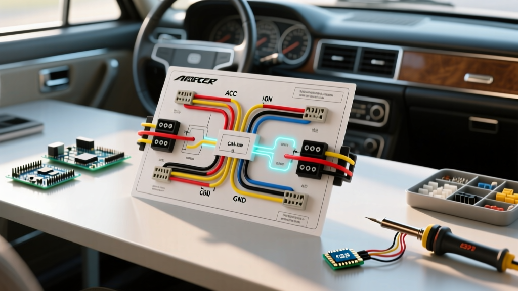
The following framework strips away the redundant accessory wiring found in OEM touring harnesses while retaining the mandatory safety circuits required for DOT compliance. This architecture utilizes a centralized power distribution block and a dedicated star-ground bus bar.
Wire Gauge & Ampacity Matrix (SAE J1128 Standard)
Standard PVC wire (like THHN) melts at sustained temperatures above 105°C. The rear cylinder of an air-cooled or Twin-Cooled Harley-Davidson routinely radiates heat exceeding 120°C in traffic. You must use Cross-Linked Polyethylene (XLPE) insulated wire, specifically TXL, GXL, or SXL automotive wire, as verified by Pacer Group technical specifications.
| Wire Gauge (AWG) | SAE Insulation Type | Max Amps (Engine Bay) | Harley Application |
|---|---|---|---|
| 10 AWG | GXL / TXL | 30A | Main Battery Feed, Stator to Regulator/Rectifier |
| 12 AWG | GXL / TXL | 20A | Headlight Relay Feed, Horn Relay, Starter Solenoid Trigger |
| 14 AWG | TXL | 15A | Taillight, Brake Light, Turn Signal Feeds |
| 16 AWG | TXL | 10A | Instrumentation, ECM Sensors, License Plate Light |
| 18 AWG | TXL | 6A | Handlebar Switch Signal Returns, LED Indicator Dash Lights |
Critical Safety Components Often Missing from Basic Diagrams
To maintain a "simple" layout without sacrificing safety, integrate these three components. They cost less than $45 combined but prevent catastrophic electrical fires and DOT violations.
- Headlight & Horn Relays (30A Bosch-style): Running 55W halogen or high-draw LED headlights directly through the handlebar dimmer switch causes the switch contacts to arc and melt. A simple diagram routes a 12AWG fused line directly from the battery to a relay, using the handlebar switch only as a low-amp trigger.
- Marine-Grade ATO/ATC Fuse Block: Do not use inline glass fuses (AGC). They suffer from internal corrosion and poor vibration resistance. A centralized 6-way waterproof ATO fuse block (e.g., Blue Sea Systems ST Blade) mounted under the seat provides a single point of diagnostic access.
- Load Equalizer or Solid-State Flasher: If converting to LED turn signals, FMVSS 108 requires a specific flash rate (60 to 120 flashes per minute). A CANbus-compatible solid-state flasher ensures the hyper-flash issue is resolved without splicing in bulky, heat-generating load resistors.
Step-by-Step Grounding & Routing Protocol
The most common failure point in custom Harley wiring is the ground circuit. Older diagrams rely on "daisy-chaining" grounds to the frame or engine cases. Because Harley frames are heavily powder-coated or painted, and engine vibrations loosen bolts, frame-grounding is unreliable.
- Install a Central Ground Bus: Mount a copper bus bar in a protected area (under the seat or behind the side cover).
- Prepare the Frame Contact: Sand away all paint, powder coat, and rust down to bare steel at the bus bar mounting location. Apply a conductive anti-corrosion compound (like No-Ox-Id A-Special) before torquing the bolt to 12 ft-lbs.
- Run Dedicated Ground Wires: Every major component (headlight, taillight, horn, R/R) gets its own dedicated 14AWG or 12AWG ground wire routed back to the central bus bar. This is known as a "Star Ground" topology.
- Seal All Terminations: Use adhesive-lined, dual-wall heat shrink (3M MDT or equivalent). When heated, the inner lining melts and seals out moisture, preventing the green copper oxide corrosion that plagues bikes washed frequently or ridden in rain.
Real-World Failure Modes & Troubleshooting
Failure Mode 1: Stator Burnout from Poor R/R Grounding
The Symptom: Battery reads 12.4V at idle but drops to 11.2V at 2,500 RPM. The stator smells of burnt varnish.
The Cause: The Regulator/Rectifier (R/R) shunts excess AC voltage from the stator to ground. If the R/R ground wire is undersized (e.g., 16AWG) or grounded to a painted engine fin, the voltage has no path to escape. It backs up into the stator windings, melting the insulation and shorting the phases.
The Fix: Ensure the R/R ground is a minimum of 12AWG GXL wire, bolted directly to a clean, bare-metal point on the engine crankcase, and tied back to the main ground bus.
Failure Mode 2: Voltage Drop on the Starter Solenoid
The Symptom: The starter solenoid clicks rapidly, but the starter motor does not engage, especially when the engine is hot.
The Cause: A simple wiring diagram often routes the starter button power through multiple connectors and handlebar switches, resulting in a voltage drop below 9V at the solenoid trigger terminal.
The Fix: Install a 30A relay for the starter solenoid. The handlebar button triggers the relay coil (drawing only 0.2A), while the relay contacts deliver a full 12V, 10AWG feed directly from the battery to the solenoid spade terminal.
Cost & Sourcing Guide for 2026
Building a safe, simplified harness from scratch is highly cost-effective compared to buying a pre-made "universal" kit that requires heavy modification.
- Wire & Terminals: 100ft spool of 14AWG TXL wire ($28), 50ft of 10AWG ($22), and a 500-piece adhesive heat shrink & ring terminal kit ($35).
- Protection & Switching: Blue Sea 6-circuit fuse block ($24), four Bosch-style 30A relays with harnesses ($18).
- Total DIY Cost: Approximately $127, yielding a custom-fit, DOT-compliant harness that weighs 40% less than the OEM equivalent.
Frequently Asked Questions
Can I use a universal 4-wire turn signal setup on a modern Harley?
No. Modern Harleys (2014 and newer) utilize a CANbus network and a Body Control Module (BCM) that expects specific resistance values from the turn signals. Splicing in generic 4-wire trailer-style converters will trigger BCM fault codes and may disable the lighting circuit. You must use a CANbus-specific load equalizer or program the BCM using Harley-Davidson's Technicians Online (T.O.S.) diagnostic software to recognize LED loads.
Is it legal to wire a brake light and taillight into a single LED unit?
Yes, provided the integrated LED unit is DOT/SAE stamped and complies with FMVSS 108. The unit must feature two distinct brightness levels: a lower-intensity "tail" circuit that is illuminated whenever the headlight is on, and a minimum 3-to-1 intensity ratio brighter "brake" circuit activated by the brake switches. Ensure you are running three wires (Ground, Tail, Brake) to the unit, not two.