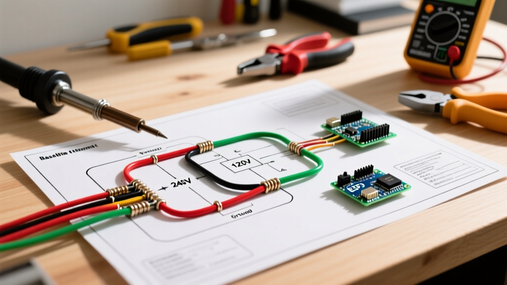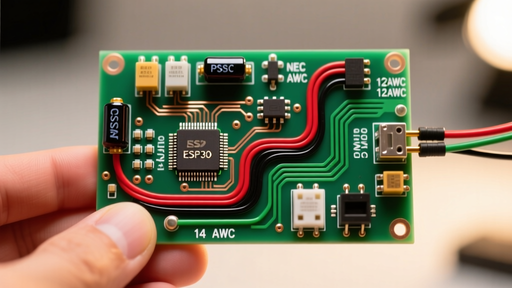

The Motor Perspective: Why Fan and Light Wiring is Unique
When approaching a wiring diagram for light and fan combinations, most DIYers focus solely on the switch leg and the neutral return. However, from an electrical engineering and motor wiring perspective, you are actually managing two entirely different load profiles on a single branch circuit. The light kit represents a purely resistive load (or a solid-state LED driver), while the ceiling fan utilizes a Permanent Split Capacitor (PSC) single-phase induction motor. Understanding how these two distinct systems interact is critical for safe, code-compliant, and long-lasting installations.
In 2026, modern ceiling fans draw significantly less current than legacy models, often pulling under 0.5 amps on high speed. Conversely, integrated LED light engines can introduce harmonic distortion or inrush currents that complicate standard dimmer and switch operations. This guide breaks down the exact motor winding configurations, capacitor routing, and National Electrical Code (NEC) requirements you need to execute a flawless installation.
Decoding the PSC Motor and Capacitor Block
Unlike universal motors found in power tools, residential ceiling fans use PSC motors because they are quiet, reliable, and do not require a centrifugal start switch. According to All About Circuits, a PSC motor relies on an auxiliary winding and a run capacitor to create the phase shift necessary to generate a rotating magnetic field.
When you look at the internal wiring diagram of a fan motor housing, you will typically find a CBB61 polypropylene film capacitor. This component is the heart of the fan's speed control.
- High Speed: Line voltage is routed directly to the main winding, bypassing the capacitor.
- Medium Speed: Line voltage passes through one section of the capacitor (e.g., 2.5µF) before reaching the auxiliary winding.
- Low Speed: Line voltage passes through both capacitor sections in series (e.g., 5.0µF total), maximizing impedance and reducing motor torque.
Expert Insight: Never substitute a standard electrolytic start capacitor for a CBB61 run capacitor. Start capacitors are designed for intermittent duty and will overheat, vent, or explode if left in the continuous circuit of a ceiling fan motor.
NEC Wire Gauge and Breaker Sizing (2026 Standards)
Before connecting the light and fan, you must verify the branch circuit wiring. Under the 2026 NEC cycle, specifically Article 210.19 and 240.4(D), overcurrent protection must strictly match the conductor ampacity. Because fans and lights are considered continuous or non-continuous lighting loads, standard residential lighting circuits apply.
| Wire Gauge (Copper) | Max Breaker Size | Typical Application | NEC Reference |
|---|---|---|---|
| 14 AWG | 15 Amps | Standard bedroom/living room lighting & fan circuits | 240.4(D)(3) |
| 12 AWG | 20 Amps | Kitchen, bathroom, or multi-fan shared circuits | 240.4(D)(4) |
| 10 AWG | 30 Amps | Not permitted for standard 15A/20A lighting receptacles | 210.21 |
AFCI Considerations: The 2026 NEC mandates Arc-Fault Circuit Interrupter (AFCI) protection for nearly all 120V, 15A and 20A branch circuits in dwelling units (Article 210.12). Be aware that older, worn fan motors can generate electrical arcing at the brushes or internal winding faults that may nuisance-trip modern combination AFCI breakers. If this occurs, the motor requires replacement, not a breaker downgrade.
Three Primary Wiring Scenarios
The physical wiring at the ceiling junction box depends entirely on the switch configuration installed on the wall. Here are the three standard setups.
Scenario A: Single Pole Switch (Pull Chain Control)
In this configuration, a single wall switch controls power to the entire fan and light unit. Speed and light toggling are managed via the physical pull chains on the fan housing.
- Line (Hot): Connect the black wire from the ceiling junction box to the both the black (fan motor) and blue (light kit) wires on the fan.
- Neutral: Connect the white ceiling wire to the white fan wire.
- Ground: Connect bare/green ceiling wire to the green fan wire and the mounting bracket.
Scenario B: Dual Switch (Independent Wall Control)
This requires a 3-wire cable (e.g., 14/3 or 12/3 Romex) running from the dual-gang wall switch to the ceiling box, providing two separate switched legs.
- Switch Leg 1 (Fan): Connect the red wire from the ceiling box to the black wire on the fan motor.
- Switch Leg 2 (Light): Connect the black wire from the ceiling box to the blue wire on the fan light kit.
- Neutral & Ground: Tie all whites together and all grounds together.
Note: Always ensure the wall switches are standard single-pole toggle or rocker switches. Do not use standard dimmers on the fan motor leg, as altering the voltage waveform will cause the PSC motor to overheat and fail prematurely.
Scenario C: Smart / Remote Receiver Module
Most modern fans, such as those from Hunter or Hampton Bay, utilize a remote receiver (e.g., UC7080T or FAN-35T) tucked into the canopy. The EPA ENERGY STAR guidelines note that these receivers manage the power splitting internally.
- Input Side (from ceiling): Connect ceiling Black (Hot) to Receiver Black, and ceiling White (Neutral) to Receiver White.
- Output Side (to fan): Match the colors exactly. Receiver Black to Fan Black, Receiver Blue to Fan Blue, Receiver White to Fan White.
- DIP Switches: Ensure the 4 DIP switches on the receiver match the remote control to prevent RF interference with neighboring units.
Troubleshooting Common Motor and Light Failures
Even with a perfect wiring diagram for light and fan execution, component failures occur. Use this diagnostic matrix to identify the root cause without blindly replacing parts.
1. Motor Hums but Will Not Spin
Failure Mode: The CBB61 run capacitor has degraded, losing its microfarad (µF) rating. Without the proper phase shift, the motor lacks starting torque.
Fix: Turn off the breaker, open the switch housing cup, and locate the black rectangular capacitor. Read the µF rating (e.g., 5µF ±5% 250VAC). Order an exact CBB61 replacement. Splice the wires using wire nuts; polarity on a CBB61 capacitor does not matter.
2. Light Flickers on Low Fan Speeds
Failure Mode: Voltage drop across a failing wall dimmer, or a loose neutral connection at the wire nut causing a floating neutral when the motor draws inrush current.
Fix: First, torque all neutral wire nuts to ensure copper-to-copper contact. If using an LED light kit, verify the wall dimmer is a trailing-edge (ELV) dimmer specifically rated for LED loads, such as the Lutron Diva DVCL-153P. Leading-edge (TRIAC) dimmers often cause PWM flickering in modern fan LED drivers.
3. Fan Runs Backwards After Capacitor Replacement
Failure Mode: The auxiliary and main winding wires were swapped at the capacitor terminals or the reverse switch is stuck in a dead-center position.
Fix: Check the physical direction switch on the fan housing. If it feels loose or lacks a distinct 'click', the internal DPDT switch is broken. If the switch is fine, verify the wiring against the manufacturer schematic printed on the motor housing sticker.
Final Safety and Code Compliance Checks
Before energizing the circuit and mounting the canopy, perform a final verification. According to the National Fire Protection Association (NFPA 70), all ceiling fan mounting boxes must be rated specifically for fan support (marked 'Acceptable for Fan Support'). Standard drywall anchor boxes will fail under the dynamic vibrational load of a spinning motor.
Furthermore, ensure that the ground wire is securely bonded to the metal mounting bracket and the fan's internal ground pigtail. A missing ground on a metal-housed fan poses a severe shock hazard if an internal winding shorts to the stator casing. By treating the light and fan not just as simple appliances, but as a combined resistive and inductive motor system, you guarantee a safe, quiet, and highly efficient installation for years to come.