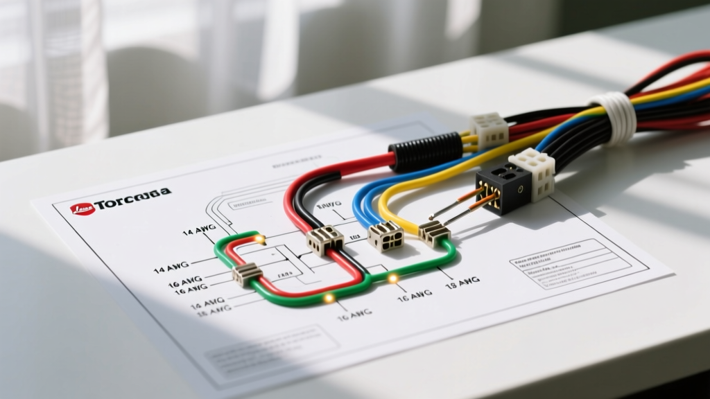

Decoding the Wiring Diagram for Toro Zero Turn Mowers
When maintaining, modifying, or repairing commercial and residential landscaping equipment, understanding the wiring diagram for Toro zero turn mowers is critical. Whether you are working on a TimeCutter 5000 series (like the 75754) or a heavy-duty Titan HD (76602), the electrical architecture relies on a 12V DC system powered by Kawasaki FR/FS or Kohler 7000 series V-Twin engines. Unlike household AC wiring, 12V DC systems are highly susceptible to voltage drop, making exact wire gauge selection and color code adherence non-negotiable for reliable operation and safety.
Standard Toro Wire Color Code Reference Chart
Toro adheres closely to standard automotive and small engine 12V DC color conventions. However, tracing a fault requires knowing exactly which color corresponds to which subsystem. Below is the definitive color code matrix used in modern Toro zero-turn harnesses.
| Wire Color | Primary Function | Typical Gauge (AWG) | Common Connection Points |
|---|---|---|---|
| Red | Main Battery Positive | 6 - 10 | Battery terminal, Starter Solenoid, Fuse Block |
| Black | Chassis Ground | 6 - 10 | Battery negative, Engine block, Frame grounding lug |
| Yellow | Stator AC Output | 14 - 16 | Engine alternator stator, Voltage Regulator/Rectifier |
| Purple | PTO Clutch Engagement | 14 | PTO switch, Safety Interlock Module (SAM), PTO Clutch coil |
| Orange | Switched 12V (Key ON) | 14 - 16 | Ignition switch, Hour meter, Accessory ports |
| White | Regulator DC Output / Lighting | 14 - 16 | Voltage Regulator, Headlight harness, Taillights |
| Green | Sensors / Safety Switches | 16 - 18 | Seat switch, PTO lever switch, Brake pedal switches |
Critical Wire Gauge Selection for 12V DC Mower Systems
A common mistake when repairing a damaged Toro harness is substituting 16 AWG wire for a circuit that requires 12 AWG. In a 12V DC system, amperage is high relative to voltage, meaning even a short run of undersized wire will cause a severe voltage drop. According to Blue Sea Systems' DC wire sizing guidelines, wire length must be calculated as the total round-trip distance (positive plus ground) to ensure the voltage drop remains below 3% for critical circuits.
Ampacity and Gauge Breakdown for Toro Subsystems
- 6 AWG to 8 AWG (Up to 60-80 Amps continuous): Reserved exclusively for the main battery cables running to the starter solenoid and the main chassis ground. On the Titan HD models with larger Kawasaki FX engines, the starter surge can exceed 150 amps momentarily; 6 AWG stranded copper is mandatory to prevent cranking failure.
- 10 AWG (Up to 30 Amps): Used for the main power feed from the solenoid to the primary fuse block and the high-amperage charging circuit output.
- 12 AWG (Up to 20 Amps): Standard for the main ignition switch power feed and high-draw accessories like 12V sprayer pumps or heavy-duty LED light bars added to the TimeCutter series.
- 14 AWG (Up to 15 Amps): The workhorse of the Toro harness. Used for the PTO clutch circuit (which typically draws 2.5 to 4.5 amps but requires 14 AWG to prevent voltage drop over the long run to the front deck), lighting circuits, and the voltage regulator input.
- 16 to 18 AWG (Up to 6-10 Amps): Used strictly for low-current logic signals, such as the Safety Interlock Module (SAM) inputs from the seat switch, steering lever neutral switches, and brake pedals.
Understanding the Voltage Regulator and Stator Circuit
The Kawasaki FX and Kohler 7000 series engines utilize a three-phase stator that outputs raw AC voltage (often 30V to 50V AC at high RPM). The yellow wires (14 AWG) carry this AC to the voltage regulator/rectifier. The regulator converts this to 14.1V - 14.4V DC, which exits on the white wire (14 AWG) to charge the battery and run the 12V system. A common failure mode is the regulator overheating due to poor grounding. The regulator case must be grounded to the engine block, and the black ground wire in the harness must have a clean, bare-metal connection. If the white wire shows 16V or higher at idle, the internal diodes in the regulator are fried, which will rapidly boil your battery dry and destroy the SAM module.
Tracing the PTO and Safety Interlock Circuit
The most frequently serviced electrical pathway on any zero-turn mower is the PTO (Power Take-Off) engagement circuit. When a Toro TimeCutter's blades fail to engage, the issue is rarely the clutch itself; it is usually a voltage drop in the harness or a failed interlock switch.
Expert Troubleshooting Tip: Never test the PTO clutch by simply checking for 12V with a standard digital multimeter. A DMM draws almost zero current and will show 12V even across a corroded, high-resistance connection. Always use an incandescent test light or a dummy load to test the PTO harness under actual amperage draw. A healthy PTO clutch needs at least 11.5V under load to engage reliably.
The safety interlock logic relies on a sequence of 18 AWG green and purple wires. If the parking brake is not set, or the steering levers are not fully in the neutral-outward position, the SAM interrupts the purple wire path to the PTO relay. When replacing these micro-switches, always use heat-shrink butt splices with adhesive-lined tubing (dual-wall heat shrink) to prevent moisture ingress, which is the leading cause of green-circuit corrosion.
Common Electrical Failure Modes in TimeCutter & Titan Models
- Chafing at the Steering Damper Mounts: The main harness routes near the hydraulic steering dampers on the TimeCutter 5000 series. Vibration causes the factory zip-ties to saw through the 14 AWG orange and white wires. Always inspect this junction and re-wrap with split loom and friction tape.
- Corroded Packard Weather-Pack Connectors: Toro uses Delphi (now Aptiv) Weather-Pack connectors for the engine-to-harness interface. Over time, the silicone seals degrade. If you see green crust on the brass terminals, do not just clean them; replace the pigtail using a proper crimping tool (like the Weather-Pack specific crimper) rather than soldering. Solder wicks into the wire and creates a brittle stress point that will snap under engine vibration.
- Voltage Drop at the Starter Solenoid: If the engine clicks but will not turn over, measure the voltage directly at the solenoid's battery-side post while cranking. If it drops below 10.5V, your 6 AWG ground cable to the frame is likely corroded at the ring terminal.
Essential Tools for Harness Repair
To properly repair a Toro zero-turn harness to OEM standards, you need more than basic wire strippers. You must use automotive-grade primary wire (SAE J1128 standard, specifically GXL or TXL cross-linked polyethylene insulation), which is designed to flex continuously without work-hardening. Invest in the following tools:
- Adhesive-Lined Heat Shrink: 3M or equivalent dual-wall tubing with a 3:1 shrink ratio. The inner meltable adhesive seals out water and fertilizer chemicals.
- Ratcheting Crimper: Specifically for open-barrel terminals (like the Amp Universal MATE-N-LOK pins used in Toro's SAM connectors). A standard automotive crimper will crush these pins and cause a short.
- Dielectric Grease: Apply a small dab of silicone dielectric grease to every multi-pin connector before mating to prevent oxidation.
Frequently Asked Questions
Where can I find the exact wiring diagram for my specific Toro model?
You can download the precise schematic by entering your model and serial number on the official Toro support manuals page. Always use the serial number, not just the model name, as mid-year production changes often alter the safety interlock wiring.
Can I use standard household solid-core wire for mower repairs?
Absolutely not. Household solid-core wire will fracture within hours due to the high-frequency vibration of the V-Twin engine and the chassis movement. You must use stranded, automotive-grade primary wire, which is engineered to withstand harsh environmental conditions and constant vibration.
Why does my Toro zero turn kill the engine when I release the brake?
This is a deliberate safety interlock function. The 18 AWG green wire from the brake switch signals the SAM. If the PTO is engaged or the steering levers are in the drive position, releasing the brake grounds the ignition coil kill wire (usually a white or black/white tracer wire), intentionally shorting the magneto to stop the engine and prevent runaway scenarios. For more on small engine electrical safety, refer to the Kohler Engines support documentation regarding magneto grounding circuits.