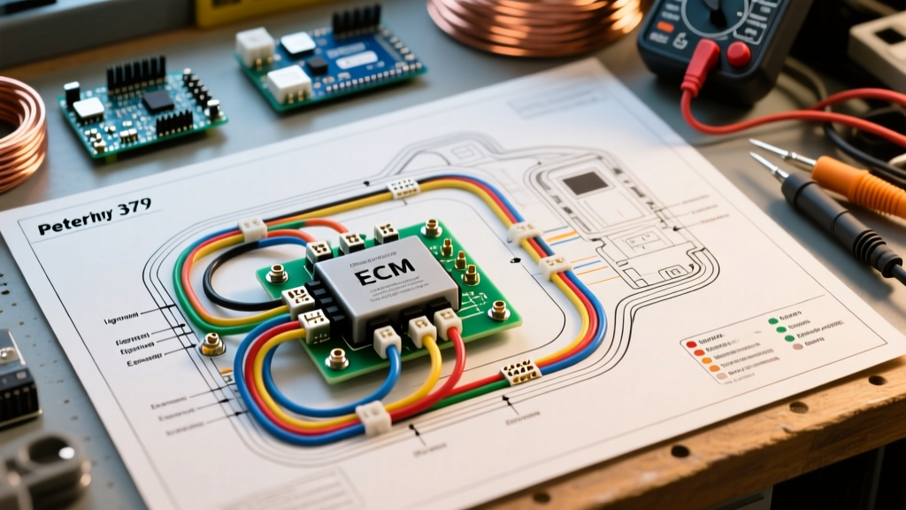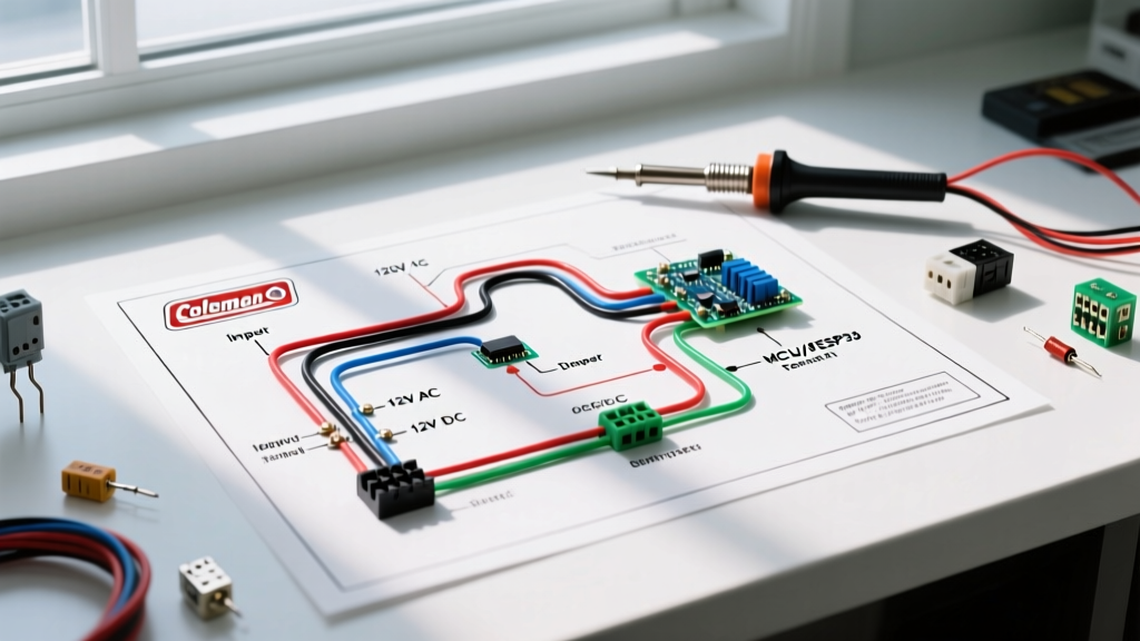

Introduction to Coleman RV AC Electrical Systems
Installing or replacing an RV air conditioning unit requires a precise understanding of dual-voltage electrical systems. When consulting a wiring diagram for Coleman RV air conditioner models—such as the ubiquitous Mach 3, the low-profile Mach 8, or the high-capacity Mach 15—you are dealing with two entirely separate circuits: a 120V AC high-voltage supply for the compressor and fan motors, and a 12V DC low-voltage control circuit for the thermostat and relays. As of 2026, Airxcel (the parent company of Coleman RV Comfort) has increasingly integrated brushless DC (BLDC) fan motors into their premium lineup, which alters the amp-draw profile and requires strict adherence to updated control board pinouts.
This comprehensive tutorial breaks down the exact wiring configurations, wire gauge requirements, and safety protocols necessary to wire a Coleman RV AC unit correctly, ensuring compliance with modern RV electrical standards and preventing catastrophic board failures.
Critical Safety Protocols and NEC Compliance
Before touching a single wire, you must isolate both power sources. RV electrical systems are governed by NFPA 70 (National Electrical Code) Article 551, which outlines specific grounding and branch circuit requirements for recreational vehicles.
- 120V AC Isolation: Turn off the main shore power breaker, disconnect the generator, and switch off the specific 20A AC branch breaker feeding the roof unit.
- 12V DC Isolation: Disconnect the RV house batteries or turn off the 12V DC main disconnect switch. The thermostat and control board operate on 12V DC, and shorting these wires can instantly fry the AC control module.
- Verification: Use a non-contact voltage tester and a digital multimeter to confirm zero voltage at the roof junction box before proceeding.
Expert Note: Never rely solely on the thermostat being in the 'Off' position to isolate power. The 12V DC logic board remains energized as long as the RV house batteries are connected, posing a severe short-circuit risk during wiring.
Dual-Voltage Architecture: 120V AC vs. 12V DC
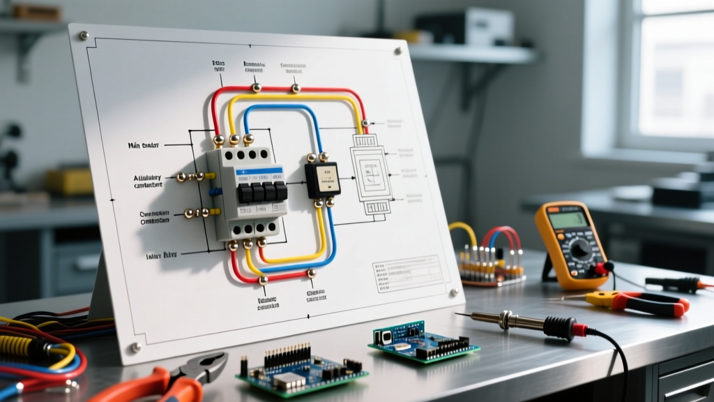
To successfully interpret the wiring diagram for Coleman RV air conditioner setups, you must separate the high-voltage power delivery from the low-voltage logic control. The Airxcel engineering specifications dictate that these systems must remain physically isolated within the junction box to prevent 120V AC from backfeeding into the 12V DC RV wiring harness, which would destroy the RV's main DC fuse panel and connected electronics.
The 120V AC Power Circuit
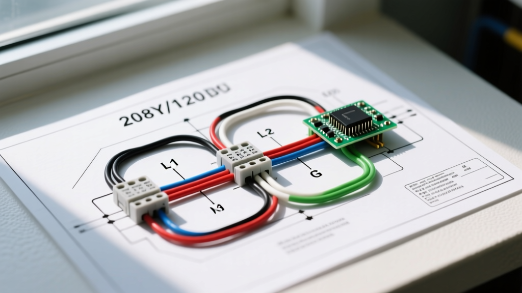
This circuit originates from your RV's main AC breaker panel and terminates at the AC unit's primary junction box. It powers the compressor contactor, the fan motor (or BLDC motor controller), and the optional 120V AC heat strip.
The 12V DC Control Circuit
This circuit runs from the RV's 12V DC fuse panel to the wall-mounted thermostat, and then up through the roof to the AC unit's control board. It powers the thermostat display, the logic relays, and the 12V DC fan mode on select 2026 Coleman models equipped with lithium-optimized power management.
Wire Gauge and Breaker Sizing Matrix
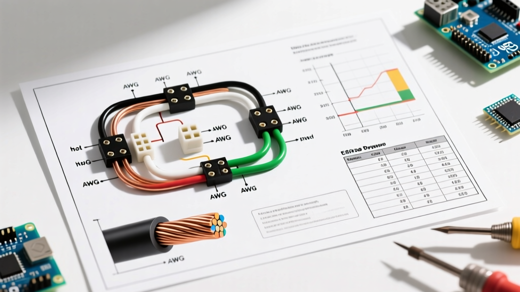
Using the correct wire gauge is non-negotiable. Voltage drop over the length of an RV (often 30+ feet from the breaker panel to the roof) can cause compressor hard-starting and relay chatter. The RV Industry Association (RVIA) mandates strict adherence to ampacity tables for mobile environments subject to high ambient roof temperatures.
| Coleman Model | Capacity | 120V Breaker | 120V Wire Gauge | 12V Control Wire |
|---|---|---|---|---|
| Mach 3 Plus (48000 Series) | 13,500 BTU | 20 Amp | 12 AWG THHN | 18 AWG (4-Wire) |
| Mach 8 (Low Profile) | 13,500 BTU | 20 Amp | 12 AWG THHN | 18 AWG (6-Wire) |
| Mach 15 (48253 Series) | 15,000 BTU | 20 Amp | 12 AWG THHN | 18 AWG (6-Wire) |
| Mach 15 w/ Heat Strip | 15,000 BTU + Heat | 20 Amp | 12 AWG THHN | 18 AWG (6-Wire) |
Note: 14 AWG wire is technically rated for 15A, but 12 AWG is the industry standard for 20A RV roof circuits to mitigate voltage drop and handle the high locked-rotor amperage (LRA) of compressor startups.
Step-by-Step 120V AC Power Wiring
When routing the 120V AC supply to the Coleman roof unit, follow this precise sequence to ensure a weatherproof and vibration-resistant connection.
- Route the Romex/THHN: Feed 12/2 AWG RV-rated stranded wire from the 20A breaker panel up through the ceiling plenum to the roof junction box. Stranded wire is mandatory in RVs to withstand highway vibration without snapping.
- Strip and Prepare: Strip 3/4 inch of insulation from the Black (Line), White (Neutral), and Bare/Green (Ground) wires.
- Grounding First: Attach the ground wire to the designated green grounding screw on the AC unit's metal chassis or the grounding bus bar inside the junction box. A poor ground will cause the GFCI breakers in the RV to trip intermittently.
- Line and Neutral Connections: Connect the Black wire to the Line (L) terminal on the control board or contactor. Connect the White wire to the Neutral (N) terminal.
- Use Wago Lever-Nuts: Do not use standard twist-on wire nuts on the roof. The constant vibration and thermal expansion/contraction will loosen them over time. Use Wago 221 series lever-nuts (rated for 32A) to splice the supply wire to the unit's pigtail wires. This is a 2026 best practice endorsed by RV master technicians.
Decoding the Thermostat Wiring Diagram
The most common point of failure when installing a Coleman RV AC is miswiring the 12V DC thermostat harness. Coleman uses a standardized color-coded harness for their analog and digital thermostats. Below is the definitive pinout guide for the standard 4-wire and 6-wire configurations.
Standard 4-Wire Configuration (Cooling Only)
- Red (R): 12V DC Positive (from RV fuse panel).
- White (W): 12V DC Ground / Common.
- Yellow (Y): Compressor / Cool Call.
- Green (G): Fan Motor High Speed.
Standard 6-Wire Configuration (Cooling + Heat Strip / Furnace)
- Red (R): 12V DC Positive.
- White (W): 12V DC Ground.
- Yellow (Y): Compressor / Cool Call.
- Green (G): Fan Motor High Speed.
- Blue (H): Heat Call (Triggers 120V AC heat strip or RV propane furnace).
- Brown (C): Fan Motor Low Speed (or auxiliary control for digital boards).
Crucial Wiring Rule: Never allow the Red (12V+) wire to touch the Yellow, Green, or Blue wires during installation. Doing so will send 12V DC directly into the logic board's microcontroller outputs, instantly destroying the board's triacs. Always cap individual wires while working.
Advanced Troubleshooting and Edge Cases
Even with a perfect wiring diagram for Coleman RV air conditioner setups, real-world conditions introduce variables. Here is how to diagnose specific electrical faults.
Compressor Hums but Fails to Start
If the 12V DC relays click and the fan starts, but the compressor emits a loud hum and trips the 20A breaker after 3 seconds, you have a start-circuit failure. First, test the dual run capacitor (typically 45+5 MFD, 370V/440VAC). If the capacitor is bulging or tests below 40 MFD on the Herm terminal, replace it. If the capacitor is fine, the compressor start winding may be open, or the shore power voltage is dropping below 104V under load, which prevents the compressor from reaching operating RPM.
Thermostat Display is Completely Blank
A blank digital thermostat indicates a loss of 12V DC power. Check the 3A or 5A automotive blade fuse located on the AC unit's main control board (usually a red or blue ATO fuse). If the fuse is blown, inspect the thermostat wiring harness for pinched wires where it passes through the roof gasket, which is a common short-circuit location.
Integrating a Hard Start Kit
For older Coleman Mach 3 and Mach 15 models operating on 30-amp RV service or off-grid inverters, installing a hard start kit (like the Micro-Air EasyStart or a generic 5-2-1 relay) is highly recommended. The hard start capacitor wires in parallel with the existing run capacitor's Herm terminal, while the potential relay wires in series with the compressor's Start (S) winding. This reduces locked-rotor amperage by up to 50%, allowing the AC to run on smaller lithium-inverter setups.
Frequently Asked Questions
Can I wire a residential smart thermostat (like Nest or Ecobee) to my Coleman RV AC?
No. Residential smart thermostats require a 24V AC control voltage provided by a residential HVAC transformer. Coleman RV systems use 12V DC from the house battery bank. Attempting to wire a 24V AC smart thermostat to a 12V DC RV system will result in a non-functional thermostat and potential damage to the RV's DC electrical system. You must use an RV-specific 12V DC smart thermostat, such as those offered by Micro-Air or RecPro.
Does the roof gasket affect the wiring?
While not an electrical component, the butyl roof gasket and the torque applied to the four interior mounting bolts dictate the compression of the wiring pass-through. If over-torqued (Coleman specifies 4-5 ft-lbs), the metal flange can crush and slice the 18 AWG thermostat wires or the 12 AWG power wires against the roof sheeting, causing a dead short to the RV chassis.
How do I wire the optional 120V AC Heat Strip?
The heat strip (usually 1,500W to 5,600 BTU) requires its own dedicated 120V AC connection on the control board, typically labeled 'HEAT'. It draws roughly 12 to 15 amps on its own. If you plan to run the heat strip and the compressor simultaneously (not recommended), you must ensure your RV's main breaker panel can handle the combined 30+ amp load without tripping the main 30A shore power pedestal breaker.