
Decoding the Schematic: Key Symbols in a Wiring Diagram for Compressor Circuits
When a residential or light-commercial HVAC system fails to cool, the compressor is often the first component suspected. However, blindly replacing a $1,200+ Copeland Scroll or Carrier reciprocating compressor without verifying the control circuit is a costly mistake. A wiring diagram for compressor circuits is your definitive roadmap. It bridges the gap between high-voltage power delivery (208/230V) and low-voltage control logic (24V). By systematically tracing the schematic, you can isolate failures to a $20 capacitor, a $15 contactor, or a burnt motor winding.
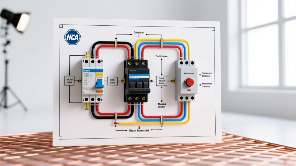
Before connecting your multimeter, familiarize yourself with the standard NEMA and IEC symbols used in modern HVAC schematics.
| Component | Schematic Symbol | Function & Common Failure Mode |
|---|---|---|
| Contactor | Relay coil with NO (Normally Open) contacts | Switches 230V to the compressor. Fails via coil burnout or contact pitting. |
| Dual Run Capacitor | Two parallel lines with a curve, labeled C, HERM, FAN | Provides phase shift for starting torque. Fails via dielectric breakdown or bulging. |
| Internal Overload | Bimetallic switch symbol inside the compressor dome | Trips on high heat/amperage. Often mistaken for an open winding. |
| Thermostat/Control | 24V switch network (Y1, C, R) | Signals the contactor coil. Fails via loss of 24V or bad relay. |
Step-by-Step Troubleshooting Using the Diagram
1. Verifying Line Voltage at the Contactor (L1/L2 to T1/T2)
According to the wiring diagram, line power enters the contactor at L1 and L2, and exits to the compressor at T1 and T2. Set your multimeter (e.g., Fluke 117) to AC Voltage.
- Measure L1 to L2: You should read between 208V and 240V. The NEC and manufacturer specs dictate that voltage must remain within 10% of the nameplate rating under load. A reading below 187V will cause the compressor to draw excessive amperage and trip the internal overload.
- Measure T1 to T2 (While Energized): If L1-L2 shows 235V, but T1-T2 shows 220V, you have a 15-volt drop across the contactor. This indicates severe contact pitting. Replace the contactor immediately (e.g., a Mars 10432 or Packard C330B, typically $15–$25 in 2026) to prevent single-phasing the compressor.
2. Testing the Dual Run Capacitor (C, HERM, FAN)
The wiring diagram routes the HERM (Hermetic) terminal to the compressor's Start (S) winding, and the C (Common) terminal to the Run (R) winding. Capacitors degrade over time due to thermal stress.
- Disconnect Power & Discharge: Use a 20k-ohm, 5-watt resistor across the terminals to safely discharge stored energy.
- Measure Capacitance: Use a meter with a dedicated capacitance setting. A standard 45/5 MFD capacitor (like the AmRad 455HQR, priced around $22–$35 in 2026) has a tolerance of ±6%. If the HERM-to-C reading drops below 40 MFD, the capacitor is failing and cannot provide the necessary phase shift to start the compressor.
- Advanced ESR Testing: In 2026, many top-tier technicians rely on Equivalent Series Resistance (ESR) meters rather than standard capacitance meters. A capacitor might read a perfect 45 MFD on a standard meter but have high internal ESR due to dried-out electrolyte, causing it to fail under the heavy inductive load of compressor startup.
- Check for Shorts: Set your meter to Ohms. Place probes on C and HERM. It should read infinite (OL). Any resistance indicates internal dielectric breakdown.
3. Checking the Compressor Windings (C, S, R)
Trace the diagram to the compressor terminal block. You will find three pins: Common (C), Start (S), and Run (R). Disconnect all wires and measure resistance.
- The Math Rule: The resistance from C to S plus the resistance from C to R must exactly equal the resistance from S to R. (e.g., C-R = 2.1Ω, C-S = 3.5Ω, S-R = 5.6Ω). If S-R does not equal the sum, there is an internal short between windings.
- Ground Fault Testing (Megger): A standard multimeter cannot detect micro-fractures in winding insulation. You must use a Megohmmeter (Megger) set to 500V DC. Measure from the C terminal to the copper suction line. As per Emerson Copeland engineering guidelines, any reading below 500 Megohms indicates insulation breakdown. A reading under 5 Megohms means the compressor is shorted to ground and has suffered a motor burnout, requiring a full system acid flush.
Common Edge Cases & Diagram Tracing
The "Humming" Compressor and Internal Overloads
If the contactor pulls in, the capacitor tests good, but the compressor only hums and draws locked-rotor amperage (LRA) before clicking off, the internal thermal overload has tripped. The wiring diagram shows this overload in series with the Common winding inside the hermetic dome. Do not attempt to bypass this. Allow 45 to 90 minutes for the internal bimetallic strip to cool and reset. If it fails to reset after cooling, the internal overload is permanently open, and the compressor must be replaced.
Single-Phasing from a Burnt Contactor
If the wiring diagram shows a 3-phase commercial unit, single-phasing is a lethal failure mode. If one pole of the 3-pole contactor fails to make contact, the compressor will run on two phases, drawing 150%+ of its rated amperage on the remaining windings. This will melt the Run winding in minutes. Always check voltage across all three phases (T1-T2, T2-T3, T1-T3) at the compressor terminals while the unit is running.
Integrating a Hard-Start Kit
For aging reciprocating compressors experiencing hard-starts (lights dimming, breaker tripping on startup), the wiring diagram can be modified to include a 5-2-1 hard-start kit (like the Supco SPP6, approx. $35). This involves wiring the kit's potential relay and start capacitor in parallel with the existing run capacitor, directly across the C and HERM terminals. This provides an extra 500% starting torque for the first 100 milliseconds of operation.
Tracing Control Logic: Crankcase Heaters and Pressure Switches
Modern wiring diagrams for compressor units include vital safety and longevity circuits that are often overlooked during basic troubleshooting. The crankcase heater is a prime example. Wired directly to the line voltage side of the contactor (often L1 and L2), its purpose is to keep the compressor oil warm during the off-cycle, preventing liquid refrigerant from migrating and condensing in the crankcase. If your diagram shows a crankcase heater, verify it is drawing the correct amperage (typically 0.5A to 1.5A). A cold crankcase on a 50°F morning will lead to liquid slugging upon startup, which can mechanically shatter the scroll plates or break the connecting rods in a reciprocating unit.
Additionally, trace the 24V control circuit through the high-pressure and low-pressure switches. These are normally closed (NC) switches wired in series with the contactor coil. If the contactor coil is receiving 0V despite the thermostat calling for cooling (Y1 energized), use your multimeter to check for voltage drops across each safety switch. An open low-pressure switch indicates a refrigerant leak, while an open high-pressure switch points to a restricted condenser coil, a failed condenser fan motor, or non-condensables (air) trapped in the system.
CRITICAL SAFETY WARNING: Always adhere to OSHA Lockout/Tagout (LOTO) standards when working inside electrical panels. Furthermore, opening the refrigerant circuit to replace a compressor requires strict adherence to EPA Section 608 regulations regarding refrigerant recovery. Never vent refrigerant to the atmosphere.
Summary of Diagnostic Workflow
A wiring diagram for compressor troubleshooting is not just a reference; it is a sequential checklist. By verifying incoming voltage, testing the phase-shifting capacitor, and mathematically validating the motor windings, you eliminate guesswork. Always cross-reference your field measurements with the specific manufacturer's schematic, as control logic (like crankcase heaters and high-pressure switches) varies significantly between brands like Trane, Lennox, and Goodman.