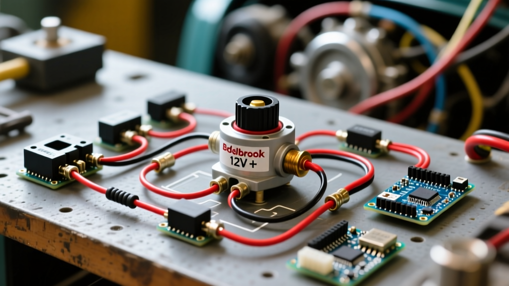

Why High-Power E-Bikes Need a DC Breaker Panel Approach
When building or upgrading a high-performance electric bicycle, the electric bike controller wiring diagram is often treated as a simple point-to-point connection between the battery and the motor drive. However, as modern e-bikes push past the 3000W to 8000W threshold—utilizing 72V battery packs and controllers like the Sabvoton 72V 165A, ASI BAC8000, or Kelly KLS-7230H—the electrical currents involved become dangerously high. A sustained draw of 120 amps or a peak surge of 250 amps can melt standard wiring and ignite lithium cells in milliseconds if a short circuit occurs.
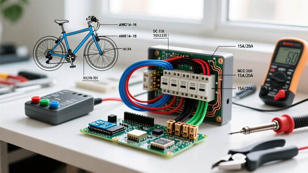
This is where applying a Panel & Breaker Guide methodology to your e-bike build becomes critical. Instead of relying solely on a basic inline fuse, serious builders design a miniature DC power distribution panel. This centralized hub manages overcurrent protection, houses the main battery cutoff, and integrates the precharge circuitry required to protect the controller's internal capacitors. In this guide, we will break down the ultimate electric bike controller wiring diagram from a professional DC panel perspective, ensuring your build is safe, efficient, and compliant with core electrical safety principles.
The Core Electric Bike Controller Wiring Diagram: Power Stage
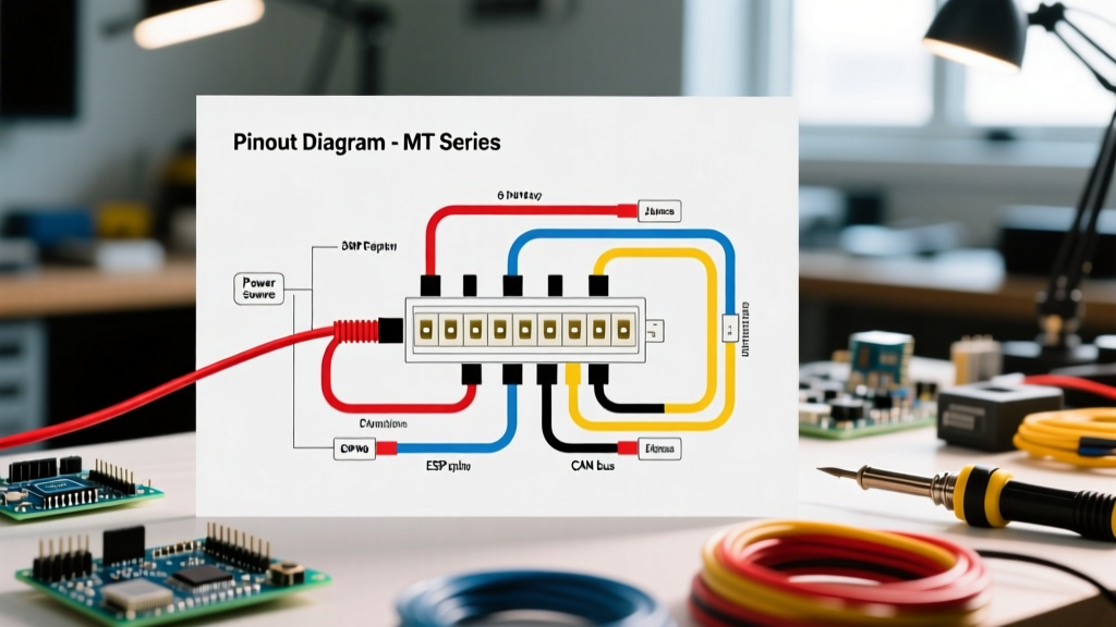
The foundation of any robust e-bike electrical system is the main power loop. Unlike standard AC household panels, a DC e-bike panel must handle continuous high-amperage loads without suffering from thermal runaway. The primary wiring diagram for the power stage flows as follows:
- Battery Positive (B+) routes to the main DC circuit breaker or ANL fuse block.
- The Breaker Output connects to the main positive busbar or the controller's primary B+ terminal.
- Battery Negative (B-) routes directly to a heavy-duty negative busbar, which then distributes to the controller B-, motor phase ground, and accessory grounds.
- A Precharge Circuit is wired in parallel with the main contactor or heavy-duty switch to manage inrush current.
By routing the positive lead through a centralized DC breaker panel (often built using marine-grade components like Blue Sea Systems busbars), you create a single, easily serviceable point of failure that protects the entire downstream wiring harness.
DC Breaker and Fuse Sizing Matrix for E-Bike Controllers
Selecting the correct overcurrent protection is the most critical step in your electric bike controller wiring diagram. Standard AC circuit breakers will violently fail if used in a 72V DC system because they lack the internal arc suppression mechanisms required to extinguish a direct current arc. According to marine and RV electrical standards outlined by Blue Sea Systems, DC breakers must be specifically rated for the system's maximum DC voltage and interrupting capacity.
Below is a sizing matrix for common high-power e-bike controllers, updated with 2026 component availability and pricing.
| Controller Model | Voltage / Peak Amps | Continuous Amps | Recommended Protection | Min. Wire Gauge |
|---|---|---|---|---|
| Sabvoton 72V 80A (MQCON) | 72V / 160A | 45A - 55A | 100A ANL Fuse (Bussmann) | 8 AWG Silicone |
| Kelly KLS-7230H | 72V / 300A | 120A - 150A | 150A Class T Fuse or 187-Series Breaker | 4 AWG Silicone |
| ASI BAC8000 | 72V / 300A+ | 150A - 180A | 200A Class T Fuse + Main Contactor | 2 AWG or Dual 4 AWG |
Cost Note: As of early 2026, a genuine Bussmann ANL fuse and holder kit costs between $25 and $35, while a marine-grade Blue Sea 187-Series DC breaker (rated for up to 48V, which is borderline for a fully charged 72V pack) retails for $55 to $70. For true 72V+ systems (which peak at 84V), Class T fuses are the mandatory choice due to their 20,000 Ampere Interrupting Capacity (AIC).
The Danger of Nuisance Tripping and Heat
When designing your panel, remember that DC breakers are thermally actuated. If you mount a 120A breaker inside an enclosed battery box where ambient temperatures exceed 110°F (43°C) during summer rides, the breaker will experience 'nuisance tripping' at currents as low as 90A. Always mount your DC breaker panel in a well-ventilated area, or uprate the breaker and rely on the Battery Management System (BMS) for primary short-circuit protection.
The Precharge Circuit: Protecting Controller Capacitors
One of the most frequently omitted elements in amateur electric bike controller wiring diagrams is the precharge circuit. High-power controllers contain massive banks of electrolytic capacitors. When a fully charged 84V battery is suddenly connected to an empty capacitor bank, the capacitors act as a dead short. The resulting inrush current can easily exceed 1,000 amps for a fraction of a second, welding your main switch contacts together and destroying the controller's internal traces.
To integrate a precharge circuit into your DC panel layout, follow this wiring sequence:
- Step 1: Wire a 150-Ohm, 5-Watt ceramic power resistor in parallel with your main battery switch or contactor.
- Step 2: When you turn on the system, the current flows first through the resistor, gently charging the controller capacitors over 2 to 4 seconds.
- Step 3: Once the voltage equalizes, close the main heavy-duty switch (or activate the contactor via a low-current dashboard switch), bypassing the resistor.
Expert Tip: If you prefer not to build a custom panel-mounted precharge circuit, use an XT90-S (Anti-Spark) connector. The XT90-S has a built-in resistor in the smaller secondary pins that makes contact milliseconds before the main power pins engage. However, for systems drawing over 120A continuous, a panel-mounted contactor with a dedicated precharge resistor is vastly superior and more reliable than relying on plastic connector pins.
Panel Termination: Crimping and Wire Routing Standards
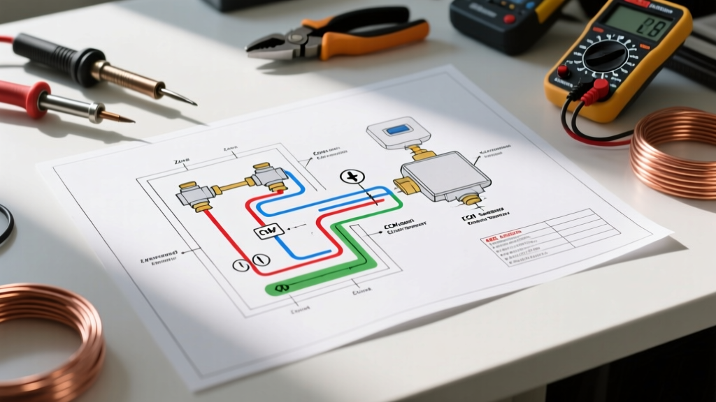
The physical execution of your electric bike controller wiring diagram is just as important as the schematic. The leading cause of e-bike electrical fires is high-resistance connections at the breaker panel lugs due to improper crimping.
Required Tooling and Materials
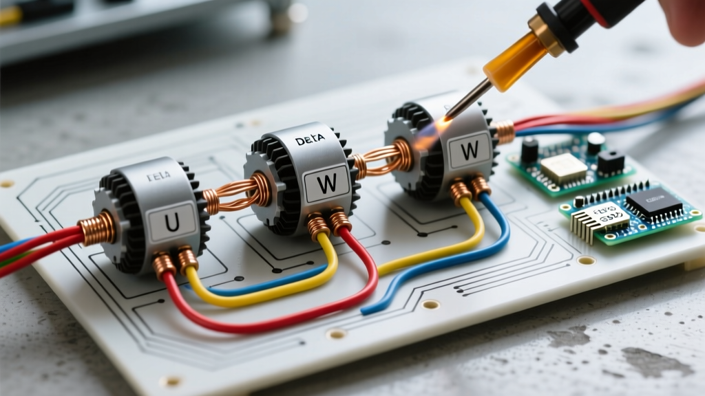
Soldering is strictly prohibited for high-amperage DC panel connections. Solder has a lower melting point than copper and can liquefy during a sustained high-load climb, causing the wire to pull out of the lug. Instead, you must use cold-weld hex crimping.
- Wire: Use only 100% copper, high-strand-count silicone wire. Avoid Copper Clad Aluminum (CCA) wire sold on cheap marketplaces; it has 40% less ampacity and will oxidize at the crimp joint.
- Crimper: Use a dedicated hex crimper, such as the IWISS IWS-16 or Titan Power Crimper. These tools compress the copper lug into a perfect hexagon, ensuring a gas-tight cold weld.
- Heat Shrink: Seal every panel termination with 3M FP-301 adhesive-lined marine heat shrink. The internal thermoplastic adhesive melts and seals the wire strands, preventing moisture ingress and copper oxidation.
Troubleshooting Edge Cases in the Power Panel
Even with a perfect electric bike controller wiring diagram, real-world variables can cause panel-level issues. Here is how to diagnose the most common edge cases:
1. Controller Undervoltage Lockout Under Load
The Symptom: Your 72V system is fully charged (84V), but when you hit full throttle, the controller cuts out and throws an undervoltage error code.
The Panel Diagnosis: You have excessive voltage drop across your DC breaker panel. A loose lug on the busbar or an undersized breaker (e.g., using an 80A breaker on a 120A load) creates massive electrical resistance. Under a 150A pull, the resistance at the panel drops the voltage reaching the controller below the 60V low-voltage cutoff. Fix: Measure the voltage directly at the battery terminals, then measure it at the controller B+/B- terminals under load. If the difference is greater than 2.5V, rebuild your panel crimps and upgrade your busbar thickness.
2. BMS Cutoff vs. Blown Main Fuse
The Symptom: The bike loses all power instantly during hard acceleration.
The Panel Diagnosis: According to battery safety guidelines published by Grin Technologies (Ebikes.ca), the Battery Management System (BMS) is designed to protect against chronic over-current and cell imbalance, but it is not fast enough to catch a dead short. If your bike simply shuts off and requires a 'wake up' via the charger or a reset button, your BMS tripped. If your bike loses power and the BMS is still outputting voltage, your main panel fuse (ANL or Class T) has blown. Always troubleshoot the BMS status light before replacing expensive panel fuses.
Final Thoughts on NEC and DC Safety Standards
While the National Electrical Code (NFPA 70) primarily governs residential and commercial AC/DC installations rather than mobile vehicles, its core principles regarding DC overcurrent protection, wire ampacity derating, and interrupting ratings are the gold standard for custom e-bike panel builders. By treating your electric bike controller wiring diagram with the same rigor as a residential DC solar panel, you eliminate the risk of thermal events and ensure your high-power build delivers reliable, uninterrupted performance on the road.